30-Minute Quick Start Guide
Follow this step-by-step guide and you’ll have your first LED blinking program running on the development board within 30 minutes.
Preparation (10–15 minutes, first time only)
Hardware Checklist
Item |
Description |
|---|---|
Dev Board / Module |
Lierda LTE-EC71X series module or development board |
SIM Card |
Activated 4G SIM card (required for networking, not needed for LED blinking) |
USB Cable |
Micro-USB or Type-C (depends on board model), for connecting to PC |
PC |
Windows 10/11 |
Software Checklist
Item |
Description |
|---|---|
SDK Source Code |
|
Code Editor |
Visual Studio Code or any text editor (only for viewing and editing source code; compilation is handled by the tool) |
USB Driver |
Download LierdaCommonUSBSetup_V3.4.6.exe, Lierda ports will appear in Device Manager after installation (Installation Guide) |
Lierda Tools (Flash Tool) |
Download lierda_upgrade_tool_latest.zip, integrates compilation and flashing (User Guide) |
Tip: You don’t need to install GCC or set up the build environment yourself — Lierda Tools includes the complete toolchain.
Step 1: Understand the SDK Structure (2 minutes)
The SDK has three layers. You only need to focus on the top user layer:
┌─────────────────────────────────────────┐
│  User Layer    examples/                │ ← Where you write code
├─────────────────────────────────────────┤
│  System Layer  components/              │ ← SDK capabilities (drivers, network, OS)
├─────────────────────────────────────────┤
│  Base Package  components/basePkg/      │ ← Communication protocol stack (read-only)
└─────────────────────────────────────────┘
User Layer: Your code goes in the
examples/directory; the entry point isvoid user_main(void)System Layer: SDK-provided drivers, FreeRTOS, MQTT/HTTP and other middleware
Base Package Layer: Communication protocol stack maintained by Lierda, separated by module model — just pick the right one
Step 2: Hardware Connection (1 minute)
Connect the development board to your PC with a USB cable:
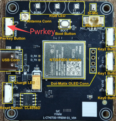
After connecting, open Windows Device Manager and verify that Lierda ports are visible (as shown below). If not, the USB driver is not installed correctly — please install the driver first.

Step 3: Identify Your Module Model (1 minute)
Check the silkscreen on the module’s shielding can to find the model number:
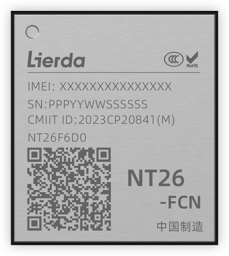
For example, if the silkscreen reads NT26F6D0, look up the corresponding base package name F6D_A in the table below:
Currently supported versions and models (latest mapping available in rules/Makefile.modem):
Base Package |
Chip |
Compatible Modules |
Notes |
|---|---|---|---|
F6C_A |
EC718PM |
NT26F6C0 |
C series general version |
F6D_A |
EC718PM |
NT26F6D0, NT26F6D0_EU, NT26F6D0_LA, NT26F6D0_NA |
D series general version |
F6D_B |
EC718PM |
NT26F6D0 |
D series VSIM general version |
F6D_GL |
EC718PM |
NT26F6D0_GL |
D series global version |
F6D_GL_B |
EC718PM |
NT26F6D0_GL |
D series VSIM global version |
F8D_A |
EC718UM |
NT26F8D0 |
D series with 8 MB Flash |
F9D_B |
EC718HM |
NT26F9D0 |
D9 series VSIM general version |
K2B_A |
EC716E |
NT26K2B1, NT26K2B3 |
B series, no full OTA support |
K2E_A |
EC716E |
NT26K2E0, NT26K2E0_0G, NT26K2E1_0G |
E series, no full OTA support |
Remember these two values for later: Module model =
NT26F6D0, Base package =F6D_A
Step 4: Configure the Project (2 minutes)
We’ll run an LED blinking demo. Two things need to be changed.
4.1 Edit the Root Makefile
Open the Makefile in the SDK root directory and find the following three variables. Set them to match your module:
export PROJECT    ?= demo
export MODEM      ?= NT26F6D0
export MODEMPKG   ?= F6D_A
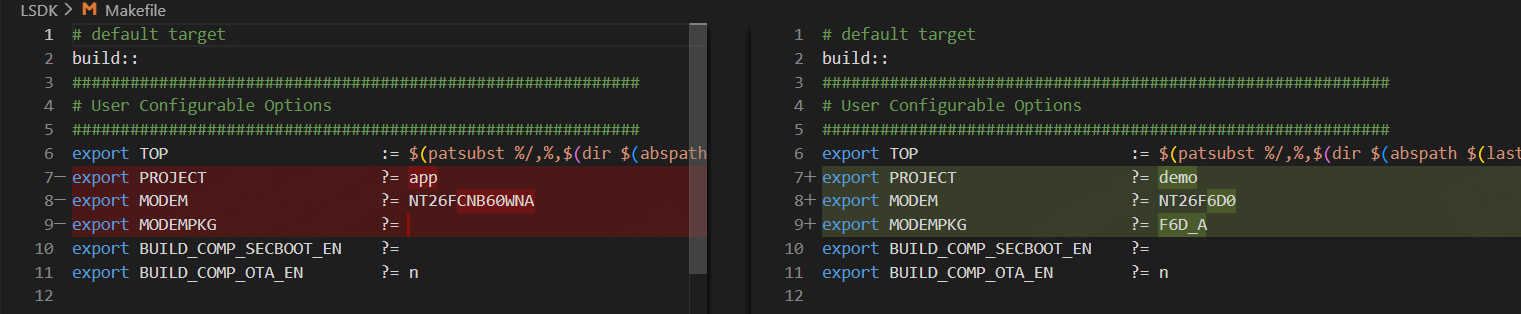
PROJECT: The project to compile — usedemohere (the built-in example project)MODEM: Your module model, use the value confirmed in the previous stepMODEMPKG: Base package name, use the value found in the previous step
4.2 Enable the LED Demo
Open the examples/demo/config file, find EXDEMO_WS2812B_EN, and set it to y:
EXDEMO_WS2812B_EN=y
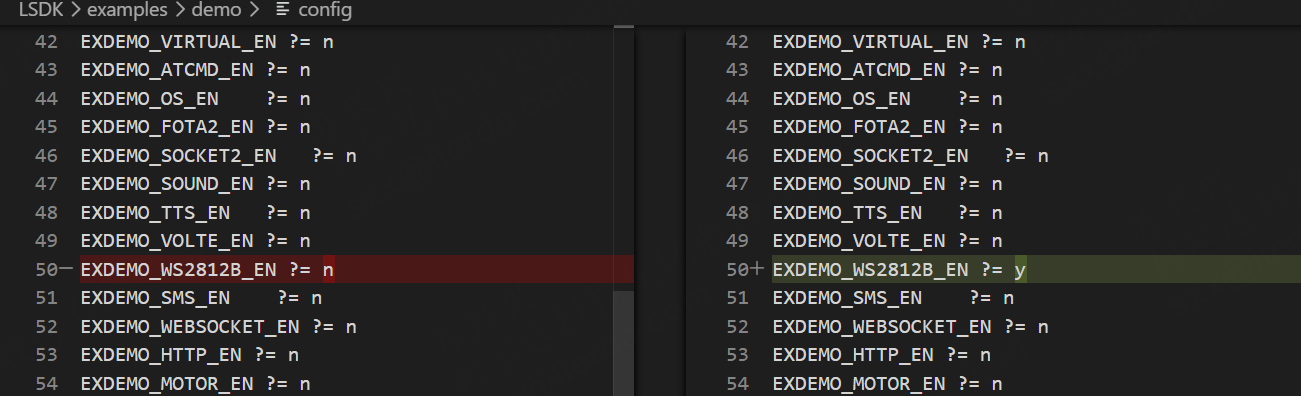
This ensures the WS2812B LED example code is included during compilation.
Checkpoint: The three Makefile variables are set correctly, and the LED demo switch is enabled in the config file.
Step 5: Build (3 minutes)
5.1 Build with Lierda Tools (Recommended)
Open Lierda Tools
Click “Browse” next to “Application Folder Path” and select the
examples/demofolder under the SDK root (e.g.,D:\CAT1.bis_OpenCPU\examples\demo)Click “Browse” next to “Base Package Path” and select the
components/basePkg/F6D_Afolder under the SDK root (matching your base package name)Click the Build button
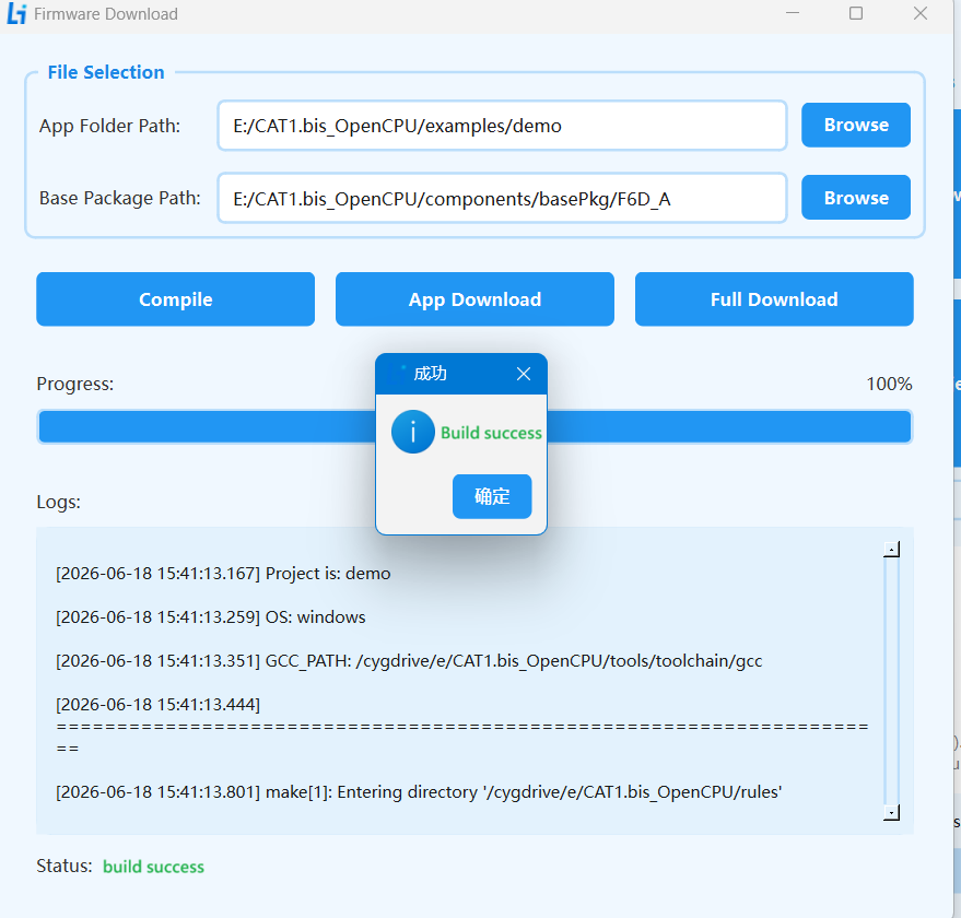
The first build takes about 1–3 minutes. A “Build Successful” message means everything is fine.
Step 6: Flash to the Development Board (2 minutes)
6.1 Enter Download Mode
Before flashing, the module must enter download mode:
Method 1: Hold the BOOT button on the board, press the RESET button (or re-plug USB), then release BOOT
Method 2: Click “Full Download” in Lierda Tools — the tool will prompt you to enter download mode, then perform the above operation
Tip: The BOOT and RESET buttons are usually located on the edge of the board with silkscreen labels nearby. If you can’t find them, check the back of the board for button annotations.
6.2 Click Full Download
Verify that the Lierda download port is visible in Device Manager
Click Full Download in Lierda Tools
The tool will automatically detect the port → flash the firmware → reboot the device upon completion
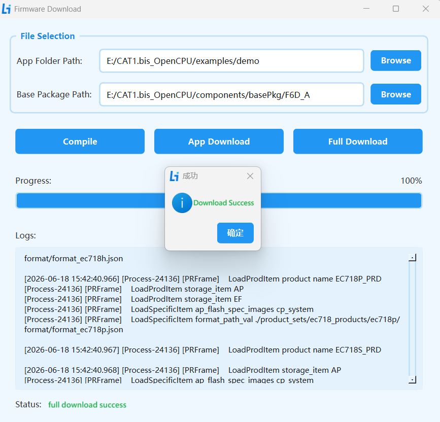
Checkpoint: Flash progress reaches 100% and the device reboots automatically.
Step 7: See the Result (1 minute)
7.1 Observe the LED
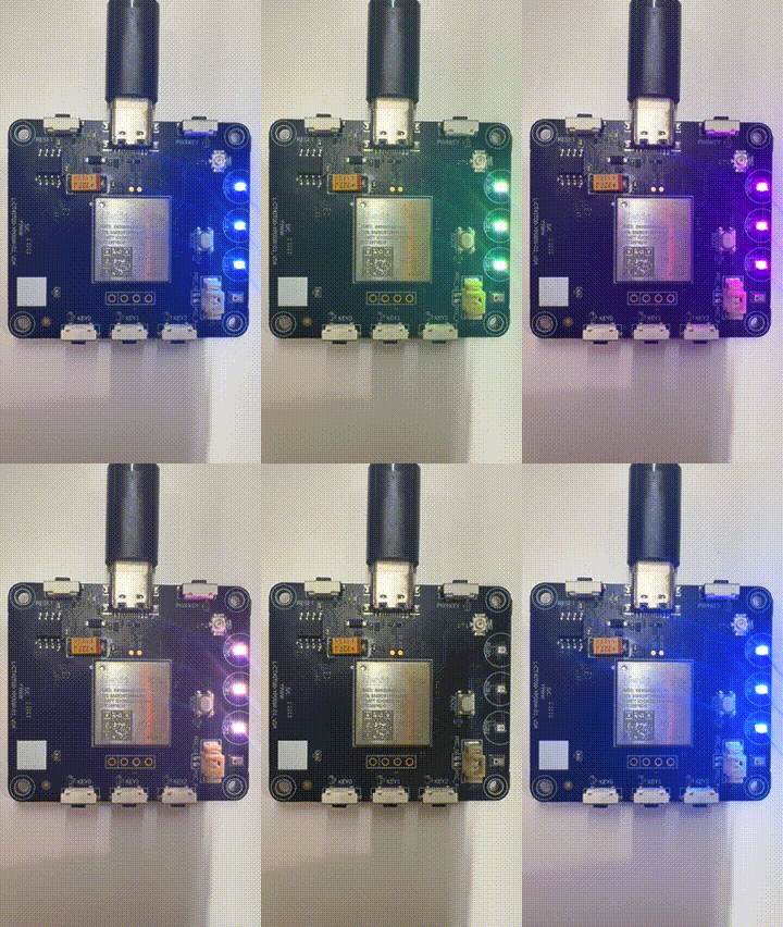
After flashing, the device reboots automatically. If everything is correct, you’ll see the WS2812B LED cycling through colors every 500ms:
The corresponding code logic (located in the examples/demo/src/ directory):
void liot_ws2812b_demo_thread(void *argv)
{
    RGBColor_TypeDef gRGBColor[WS2812B_LED_NUM] = {0};
    uint8_t R = 0x00, G = 0x00, B = 0x00;

    ws2812b_init();

    while(1)
    {
        for(int i = 0; i < WS2812B_LED_NUM; i++) {
            RGBColor_Set(gRGBColor, i, R, G, B);
        }
        ws2812b_send_data(gRGBColor, WS2812B_LED_NUM);
        R += 0x20;  if(R > 0xff) R = 0x00;
        G += 0x40;  if(G > 0xff) G = 0x00;
        B += 0x60;  if(B > 0xff) B = 0x00;

        liot_rtos_task_sleep_ms(500);
    }
    liot_rtos_task_delete(NULL);
}
7.2 View Serial Logs
To confirm the program is running, you can check the serial log output:
Open Lierda Tools
Select the COM port corresponding to
Lierda At PortSet baud rate to
115200Click the Start Print button
After the program starts, the serial port will print something like (values may vary depending on actual memory conditions):
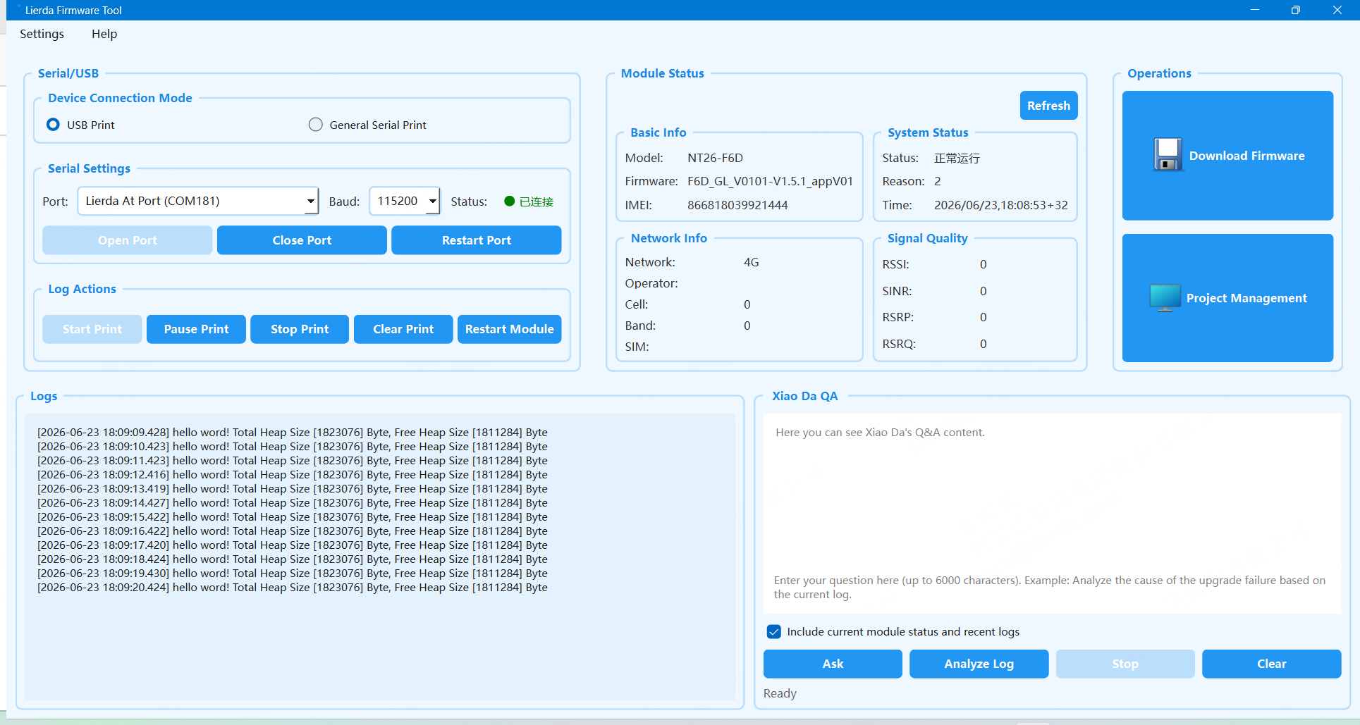
hello word! Total Heap Size [xxxxx] Byte, Free Heap Size [xxxxx] Byte
Seeing this log confirms your program is running successfully.
What’s Next
Congratulations! You’ve completed the entire process from zero to blinking LED. Choose your next direction based on your project needs:
FAQ
Symptom |
Possible Cause |
Solution |
|---|---|---|
Lierda ports not visible in Device Manager |
USB driver not installed or installation failed |
Reinstall USB driver and restart PC; make sure you’re using a data cable, not a charging-only cable |
Build error |
|
Check that it’s set to |
Build error: base package not found |
|
Verify the base package name from Step 3; confirm the folder exists under |
Port not detected during flashing |
Device not in download mode |
Retry: hold BOOT → press RESET → release BOOT; or try a different USB cable |
Flash successful but LED doesn’t light up |
LED demo switch not enabled in config, or board has no WS2812B LED |
Confirm |
Flash successful but no serial log output |
Wrong COM port or incorrect baud rate |
Confirm you selected the COM port for |
SDK path contains Chinese characters or spaces after extraction |
Toolchain doesn’t support Chinese characters in paths |
Extract SDK to a pure English path with no spaces, e.g., |
Still stuck? Join the Lierda technical support group for help, or submit an Issue on the GitHub / Gitee repository.
Want to try other demos?
Edit the examples/demo/config file, set the desired feature switch to y, then rebuild and flash. For example, to try MQTT:
EXDEMO_MQTT_EN=y
Want to develop your own project?
It’s recommended to start from the examples/app project. Copy the app directory and rename it to your project name, write your logic in user_main.c, and change PROJECT in the Makefile to your project name.
Feature Development Reference:
Direction |
Recommended Documentation |
|---|---|
GPIO / PWM / ADC Peripheral Control |
|
UART / SPI / I2C Communication |
|
Network Data Call |
|
MQTT / HTTP Cloud Communication |
|
Socket / SSL Network Programming |
|
File System |
|
Low Power Optimization |
|
OTA Remote Upgrade |
|
TTS Voice Playback |
|
Audio |
|
Secure Boot |
|
Full API Reference |
|
Hardware Pin Assignment |
|
System Resources & Chip Specifications |
Tool Documentation:
Tool |
Documentation |
|---|---|
Flash Tool Detailed Usage |
|
USB Driver Installation |
|
Log Capture & Analysis |
|
Dump Analysis |
|
Packet Capture & Debugging |