SPI Development Guide_Rev1.0
Revision History
Version |
Date |
Author |
Revision Content |
|---|---|---|---|
Rev1.0 |
23-09-11 |
TL |
Initial document creation |
Rev1.1 |
24-03-25 |
SXX |
Changed document name |
Rev1.2 |
25-01-14 |
YMX |
1. Added reference pin multiplexing table description for different modules supporting SPI |
Rev1.3 |
25-04-18 |
Zhang Hao |
Added common issues section |
Rev1.4 |
26-04-22 |
ZXQ |
Modified according to review |
1 Introduction
1.1 Document Introduction
This document introduces the LTE-EC71X SPI interface APIs. The API interfaces are declared in the file: components/kernel/lierda_api/liot_spi/liot_spi.h.
The LTE-EC71X series modules support up to 2 SPI channels. For SPI support on different modules, please refer to the corresponding “Pin Multiplexing Table”.
1.2 SPI Bus Principle Introduction
Serial Peripheral Interface (SPI) is a synchronous serial communication interface used for full-duplex, high-speed data transmission between microcontrollers and peripheral devices.
The LTE-EC71X series modules support up to 2 SPI buses (SPI0 and SPI1), each SPI supports the following functional features:
Main Functional Features:
Full-duplex synchronous communication: Supports simultaneous sending and receiving of data
Master-slave mode: Supports master-slave mode operation
Multi-slave support: Each SPI supports up to 2 chip selects (CS0, CS1)
Configurable clock frequency: Supports multiple clock frequencies: 812.5KHz, 1.625MHz, 3.25MHz, 6.5MHz, 13MHz
Flexible data frame format: Data frame size is configurable (4~16 bits, default 8 bits)
Multiple transmission modes: Supports polling, interrupt, and DMA transmission methods
Configurable clock polarity and phase: Supports 4 SPI working modes (CPOL/CPHA combinations)
MSB first transmission: Data is always transmitted with the Most Significant Bit (MSB) first
Communication Interfaces:
MOSI: Master Output, Slave Input
MISO: Master Input, Slave Output
SCLK: Serial Clock, generated by master device
CS: Chip Select signal, active low (configurable)
2 API Function Overview
Function |
Description |
|---|---|
|
This function is used to initialize SPI |
|
This function is used to initialize SPI (configure SPI bus parameters) |
|
This function is used to simultaneously send and receive data through SPI |
|
This function is used to receive data through SPI |
|
This function is used to send data through SPI |
|
This function is used to release SPI bus |
3 Type Descriptions
3.1 liot_errcode_spi_e
SPI API execution result error codes.
Definition
typedef enum
{
    LIOT_SPI_SET_CB_ERR = -1,
    LIOT_SPI_SUCCESS    = 0,
    LIOT_SPI_ERROR = 1 | (LIOT_COMPONENT_BSP_SPI << 16), // Other SPI bus errors
    LIOT_SPI_PARAM_TYPE_ERROR,                           // Parameter type error
    LIOT_SPI_PARAM_DATA_ERROR,                           // Parameter data error
    LIOT_SPI_PARAM_ACQUIRE_ERROR,                        // Parameter cannot be acquired
    LIOT_SPI_PARAM_NULL_ERROR,                           // Parameter NULL error
    LIOT_SPI_DEV_NOT_ACQUIRE_ERROR,                      // Cannot acquire SPI bus
    LIOT_SPI_PARAM_LENGTH_ERROR,                         // Parameter length error
    LIOT_SPI_MALLOC_MEM_ERROR,                           // Memory allocation error
    LIOT_SPI_ADDR_ALIGNED_ERROR,                         // Address not 4-byte aligned
    LIOT_SPI_MUTEX_CREATE_ERROR,                         // Mutex creation failed
    LIOT_SPI_MUTEX_LOCK_ERROR,                           // Mutex lock timeout
    LIOT_SPI_UNKNOWN_ERROR,
} liot_errcode_spi_e;
Parameters
LIOT_SPI_SET_CB_ERR: Failed to set callback.LIOT_SPI_SUCCESS: Function executed successfully.LIOT_SPI_ERROR: Function execution failed.LIOT_SPI_PARAM_TYPE_ERROR: Parameter type error.LIOT_SPI_PARAM_DATA_ERROR: Parameter data error.LIOT_SPI_PARAM_ACQUIRE_ERROR: Parameter cannot be acquired.LIOT_SPI_PARAM_NULL_ERROR: Pointer parameter is NULL.LIOT_SPI_DEV_NOT_ACQUIRE_ERROR: Cannot acquire SPI bus.LIOT_SPI_PARAM_LENGTH_ERROR: Parameter length error.LIOT_SPI_MALLOC_MEM_ERROR: Memory allocation error.LIOT_SPI_ADDR_ALIGNED_ERROR: Address not 4-byte aligned (this error usually occurs in DMA transmission mode)LIOT_SPI_MUTEX_CREATE_ERROR: Mutex creation failed.LIOT_SPI_MUTEX_LOCK_ERROR: Mutex lock timeout.LIOT_SPI_UNKNOWN_ERROR: Unknown error.
3.2 liot_spi_config_s
SPI bus parameter configuration structure is defined as follows:
Definition
typedef struct{
    liot_spi_input_mode_e input_mode;
    liot_spi_port_e port;
    unsigned int framesize;
    liot_spi_clk_e spiclk;
    liot_spi_cs_pol_e cs_polarity0;
    liot_spi_cs_pol_e cs_polarity1;
    liot_spi_cpol_pol_e cpol;
    liot_spi_cpha_pol_e cpha;
    liot_spi_input_sel_e input_sel;
    liot_spi_transfer_mode_e transmode;
    liot_spi_cs_sel_e cs;
    liot_spi_clk_delay_e clk_delay;
    liot_spi_device_mode_e device_mode;
    liot_spi_data_msb_lsb_e data_msb_lsb;
    liot_spi_irq_callback irq_callback;
} liot_spi_config_s;
Parameters
Type |
Parameter |
Description |
|---|---|---|
liot_spi_input_mode_e |
input_mode |
SPI input function |
liot_spi_port_e |
port |
SPI bus number, only supports LIOT_SPI_PORT0 and LIOT_SPI_PORT1 |
unsigned int |
framesize |
Data frame size. Range: 4~16; Default: 8; Unit: bit |
liot_spi_clk_e |
spiclk |
SPI clock frequency |
liot_spi_cs_pol_e |
cs_polarity0 |
CS0 pin level |
liot_spi_cs_pol_e |
cs_polarity1 |
CS1 pin level |
liot_spi_cpol_pol_e |
cpol |
Clock polarity |
liot_spi_cpha_pol_e |
cpha |
Clock phase |
liot_spi_input_sel_e |
input_sel |
Data input pin |
liot_spi_transfer_mode_e |
transmode |
SPI transmission mode |
liot_spi_cs_sel_e |
cs |
CS pin |
liot_spi_clk_delay_e |
clk_delay |
MISO delay sampling |
liot_spi_device_mode_e |
device_mode |
Master-slave mode and master-slave simplex mode selection |
liot_spi_data_msb_lsb_e |
data_msb_lsb |
msb first or lsb first |
liot_spi_irq_callback |
irq_callback |
SPI transfer completion callback function |
3.3 liot_spi_input_mode_e
SPI input function enumeration is defined as follows:
Definition
typedef enum{
    LIOT_SPI_INPUT_FALSE, // SPI does not allow input (read)
    LIOT_SPI_INPUT_TRUE,  // SPI allows input (read)
} liot_spi_input_mode_e;
Parameters
LIOT_SPI_INPUT_FALSE: Disable SPI input (read) function.LIOT_SPI_INPUT_TRUE: Enable SPI input (read) function.
3.4 liot_spi_port_e
SPI bus number enumeration is defined as follows:
Definition
typedef enum{
    LIOT_SPI_PORT0, // SPI0 bus
    LIOT_SPI_PORT1, // SPI1 bus
} liot_spi_port_e;
Parameters
LIOT_SPI_PORT0: SPI0 bus.LIOT_SPI_PORT1: SPI1 bus.
3.5 liot_spi_clk_e
SPI clock frequency enumeration is defined as follows:
Definition
typedef enum{
    LIOT_SPI_CLK_INVALID  = -1,       // Invalid clock selection
    LIOT_SPI_CLK_812_5KHZ = 812500,   // Clock: 812.5K
    LIOT_SPI_CLK_1_625MHZ = 1625000,  // Clock: 1.625M
    LIOT_SPI_CLK_3_25MHZ  = 3250000,  // Clock: 3.125M
    LIOT_SPI_CLK_6_5MHZ   = 6500000,  // Clock: 6.5M
    LIOT_SPI_CLK_13MHZ    = 13000000, // Clock: 13M
} liot_spi_clk_e;
Parameters
LIOT_SPI_CLK_INVALID: Invalid parameter.LIOT_SPI_CLK_812_5KHZ: Clock frequency is 812.5 kHz.LIOT_SPI_CLK_1_625MHZ: Clock frequency is 1.625 MHz.LIOT_SPI_CLK_3_25MHZ: Clock frequency is 3.25 MHz.LIOT_SPI_CLK_6_5MHZ: Clock frequency is 6.5 MHz.LIOT_SPI_CLK_13MHZ: Clock frequency is 13 MHz.
Note: These enumeration values are just some commonly used clock frequencies. Others are also supported. You can directly configure the corresponding values, such as 10k (10000), 80k (80000), etc.
3.6 liot_spi_cs_pol_e
CS pin level enumeration is defined as follows:
Declaration
typedef enum{
        LIOT_SPI_CS_ACTIVE_HIGH, // During SPI bus operation, CS pin is high
        LIOT_SPI_CS_ACTIVE_LOW,  // During SPI bus operation, CS pin is low
    } liot_spi_cs_pol_e;
Parameters
LIOT_SPI_CS_ACTIVE_HIGH: During SPI bus operation, CS pin is high.
LIOT_SPI_CS_ACTIVE_LOW: During SPI bus operation, CS pin is low.
3.7 liot_spi_cpol_pol_e
Clock polarity enumeration is defined as follows:
Declaration
typedef enum{
        LIOT_SPI_CPOL_LOW = 0, // When SPI is disabled, CLK line is low level, first edge is rising edge
        LIOT_SPI_CPOL_HIGH,    // When SPI is disabled, CLK line is high level, first edge is falling edge
    } liot_spi_cpol_pol_e;
Parameters
LIOT_SPI_CPOL_LOW: When SPI is disabled, CLK line is low level, first edge is rising edge.
LIOT_SPI_CPOL_HIGH: When SPI is disabled, CLK line is high level, first edge is falling edge.
3.8 liot_spi_cpha_pol_e
Clock phase enumeration is defined as follows:
Declaration
typedef enum{
        LIOT_SPI_CPHA_1Edge, // Sample on first edge
        LIOT_SPI_CPHA_2Edge,  // Sample on second edge
    } liot_spi_cpha_pol_e;
Parameters
LIOT_SPI_CPHA_1Edge: Data sampling starts from the first clock edge.
LIOT_SPI_CPHA_2Edge: Data sampling starts from the second clock edge.
3.9 liot_spi_input_sel_e
Data input pin enumeration is defined as follows:
Declaration
typedef enum{
        LIOT_SPI_DI_0 = 0, // Select DI0 as data input pin, not use now
        LIOT_SPI_DI_1,     // Select DI1 as data input pin
        LIOT_SPI_DI_2,     // Select DI2 as data input pin, not use now
    } liot_spi_input_sel_e;
Parameters
LIOT_SPI_DI_0: DI0 is data input pin (currently not supported)
LIOT_SPI_DI_1: DI1 is data input pin
LIOT_SPI_DI_2: DI2 is data input pin (currently not supported)
Note: MISO pin currently does not support configuration, use default DI1.
3.10 liot_spi_transfer_mode_e
SPI transmission mode enumeration is defined as follows:
Declaration
typedef enum{
        LIOT_SPI_DIRECT_POLLING = 0, // FIFO read/write, polling wait
        LIOT_SPI_DIRECT_IRQ,         // FIFO read/write, interrupt notification
        LIOT_SPI_DMA_IRQ,            // DMA read/write, interrupt notification
    } liot_spi_transfer_mode_e;
Parameters
LIOT_SPI_DIRECT_POLLING: FIFO read/write, polling wait.
LIOT_SPI_DIRECT_IRQ: FIFO read/write, interrupt notification.
LIOT_SPI_DMA_IRQ: DMA read/write, interrupt notification.
3.11 liot_spi_cs_sel_e
CS pin enumeration is defined as follows:
Declaration
typedef enum{
        LIOT_SPI_CS0 = 0, // Select cs0 as SPI chip select CS pin
        LIOT_SPI_CS1,     // Select cs1 as SPI chip select CS pin
        LIOT_SPI_CS2,     // Select cs2 as SPI chip select CS pin, not use now
        LIOT_SPI_CS3,     // Select cs3 as SPI chip select CS pin, not use now
    } liot_spi_cs_sel_e;
Parameters
LIOT_SPI_CS0: CS0 is SPI’s CS pin.
LIOT_SPI_CS1: CS1 is SPI’s CS pin.
LIOT_SPI_CS2: CS2 is SPI’s CS pin (currently not supported).
LIOT_SPI_CS3: CS3 is SPI’s CS pin (currently not supported).
3.12 liot_spi_clk_delay_e
MISO delay sampling enumeration is defined as follows:
Declaration
typedef enum{
        LIOT_SPI_CLK_DELAY_0 = 0,  // No delay, default state
        LIOT_SPI_CLK_DELAY_1,      // MISO delay one edge sampling
    } liot_spi_clk_delay_e;
Parameters
LIOT_SPI_CLK_DELAY_0: MISO no delay sampling.
LIOT_SPI_CLK_DELAY_1: MISO delay one clock edge sampling.
3.13 liot_spi_device_mode_e
Device mode enumeration is defined as follows:
Declaration
typedef enum
    {
        LIOT_SPI_DEVICE_MODE_INVALID = 0,
        LIOT_SPI_DEVICE_MODE_MASTER, // SPI master mode, full duplex
        LIOT_SPI_DEVICE_MODE_SLAVE,  // SPI slave mode, full duplex
        LIOT_SPI_DEVICE_MODE_MASTER_SIMPLEX, // SPI master mode, half duplex, shared MOSI for transmit/receive
        LIOT_SPI_DEVICE_MODE_SLAVE_SIMPLEX,  // SPI slave mode, half duplex, shared MISO for transmit/receive
    } liot_spi_device_mode_e;
Parameters
LIOT_SPI_DEVICE_MODE_INVALID: Invalid mode
LIOT_SPI_DEVICE_MODE_MASTER: Master mode
LIOT_SPI_DEVICE_MODE_SLAVE: Slave mode
LIOT_SPI_DEVICE_MODE_MASTER_SIMPLEX: Master mode, half duplex, shared MOSI for transmit/receive
LIOT_SPI_DEVICE_MODE_SLAVE_SIMPLEX: Slave mode, half duplex, shared MISO for transmit/receive
3.14 liot_spi_data_msb_lsb_e
MSB/LSB enumeration is defined as follows:
Declaration
typedef enum
    {
        LIOT_SPI_DATA_MSB_LSB = 0,  // MSB first
        LIOT_SPI_DATA_LSB_MSB,      // LSB first
    } liot_spi_data_msb_lsb_e;
Parameters
LIOT_SPI_DATA_MSB_LSB: MSB first
LIOT_SPI_DATA_LSB_MSB: LSB first
3.15 liot_spi_irq_callback
Callback type is defined as follows:
Declaration
typedef void (*liot_spi_irq_callback)(uint32_t event);
Parameters
This is a function pointer. After SPI transfer is completed, this function will be called back in the interrupt.
4 API Function Details
4.1 liot_spi_init
This function is used to initialize SPI and should be called before using other SPI APIs. Before calling this function, you need to set the specified GPIO pin to SPI function through liot_pin_set_func (refer to demo call for details).
The default configuration of liot_spi_config_s is as follows:
struct liot_spi_config_s defaultCfg{
    .input_mode = LIOT_SPI_INPUT_TRUE,       // Enable read function
    .framesize = 8,                          // Number of bits per transmission
    .cs_polarity0 = LIOT_SPI_CS_ACTIVE_LOW,  // cs0 active low
    .cs_polarity1 = LIOT_SPI_CS_ACTIVE_LOW,  // cs1 active low
    .cpol = LIOT_SPI_CPOL_LOW,               // SPI clk initial level is low
    .cpha = LIOT_SPI_CPHA_1Edge,             // Sample on first spi clk edge, rising edge
    .input_sel = LIOT_SPI_DI_1,              // MISO uses default pin, cannot configure others
    .cs = LIOT_SPI_CS0,                      // Use CS0
    .clk_delay = LIOT_SPI_CLK_DELAY_0        // No delay for sampling
};
Declaration
liot_errcode_spi_e liot_spi_init(liot_spi_port_e port,
                                   liot_spi_transfer_mode_e transmode,
                                   liot_spi_clk_e spiclk);
Parameters
port: [In] SPI bus number.
transmode: [In] SPI transmission mode.
spiclk: [In] SPI clock frequency.
Return Value
liot_errcode_spi_e: Execution result code, see 3.1 for reference.
4.2 liot_spi_init_ext
This function is used to initialize SPI (configure SPI bus parameters) and should be called before using other SPI APIs.
This function can be used to select SPI bus, configure SPI input function, clock frequency, data frame size, CS pin and pin level, clock polarity, clock phase, data input pin, transmission mode, and MISO delay sampling. Before calling this function, you need to set related GPIO pins to SPI function through liot_pin_set_func().
Declaration
liot_errcode_spi_e liot_spi_init_ext(liot_spi_config_s spi_config);
Parameters
spi_config: [In] SPI bus parameter configuration.
Return Value
liot_errcode_spi_e: Execution result code, see 3.1 for reference.
Note: There are two initialization functions, liot_spi_init and liot_spi_init_ext. The difference is that liot_spi_init can only configure port, transmission mode, and clk;
While liot_spi_init_ext function can configure all SPI-related settings through the liot_spi_config_s structure.
4.3 liot_spi_write_read
This function is used to simultaneously send and receive data through SPI (full-duplex mode, simultaneous send and receive, must have send buffer and receive buffer).
Declaration
liot_errcode_spi_e liot_spi_write_read(liot_spi_port_e port,
                                        unsigned char *inbuf,
                                        unsigned char *outbuf,
                                        unsigned int len);
Parameters
port: [In] SPI bus number.
inbuf: [Out] Received data.
outbuf: [In] Data to send.
len: [In] Length of data to send and receive.
Return Value
liot_errcode_spi_e: Execution result code, see 3.1 for reference.
4.4 liot_spi_read
This function is used to receive data through SPI.
Declaration
liot_errcode_spi_e liot_spi_read(liot_spi_port_e port,
                          unsigned char *buf,
                          unsigned int len);
Parameters
port: [in] SPI bus number.
buf: [Out] Received data.
len: [In] Length of received data. Unit: bytes.
Return Value
liot_errcode_spi_e: Execution result code, see 3.1 for reference.
4.5 liot_spi_write
This function is used to send data through SPI.
Declaration
liot_errcode_spi_e liot_spi_write(liot_spi_port_e port,
                          unsigned char *buf,
                          unsigned int len);
Parameters
port: [In] SPI bus number.
buf: [In] Data to send.
len: [In] Length of data to send. Unit: bytes.
Return Value
liot_errcode_spi_e: Execution result code, see 3.1 for reference.
4.6 liot_spi_release
This function is used to release SPI bus.
Declaration
liot_errcode_spi_e liot_spi_release(liot_spi_port_e port);
Parameters
port: [In] SPI bus number.
Return Value
liot_errcode_spi_e: Execution result code, see 3.1 for reference.
5 Code Example
5.1 Sample Code Reference
Refer to LSDK/examples/demo/src/demo_spi.c file.
#include "lierda_app_main.h"
#include "liot_gpio2.h"
#include "liot_os.h"
#include "liot_spi.h"
#include <string.h>

// Define SPI pin configurations for different chips
#define LIOT_CUR_SPI0_MOSI_PIN_MUN (85)
#define LIOT_CUR_SPI0_MISO_PIN_MUN (84)
#define LIOT_CUR_SPI0_CLK_PIN_MUN  (86)
#define LIOT_CUR_SPI0_CS0_PIN_MUN  (83)
#define LIOT_CUR_SPI_PIN_FUNC      (1)


/** @brief Switch for testing SPI master mode, 1 for enabled, 0 for disabled */
#define SPI_MASTER_DEMO 0

/** @brief Switch for testing SPI slave mode, 1 for enabled, 0 for disabled */
#define SPI_SLAVE_DEMO  1

/** @brief Clock speed for SPI testing */
#define SPI_DEMO_CLK_SPEED          8000000U

/** @brief Length of test data */
#define TEST_DATA_LEN              (128)

/** @brief Test data buffer for writing */
unsigned char demo_data_w[TEST_DATA_LEN] = {0};

/** @brief Test data buffer for reading */
unsigned char demo_data_r[TEST_DATA_LEN] = {0};

/**
 * @brief Transfer completion flag in SPI slave mode
 */
uint8_t isTransferDone = 0;

/**
 * @brief Interrupt callback function in SPI slave mode
 *        This function is called when the SPI transfer is completed or an error occurs.
 * @param event Event flag indicating the transfer status
 */
void liot_spi_demo_callback(uint32_t event)
{
    uint8_t i = 0;
    if(event & LIOT_SPI_EVENT_TRANSFER_COMPLETE)
    {
        isTransferDone = 1;
    }
    else
    {
        liot_trace("spi_demo_callback error %d", event);
        for(i = 0; i < TEST_DATA_LEN; i++)
        {
            liot_trace("[%d]Input:0x%x", i, demo_data_r[i]);
        }
    }
}

/**
 * @brief Thread function for SPI master mode testing
 *        This function initializes the SPI master mode and performs data write and read operations in a loop.
 * @param argv Thread parameters
 */
#if SPI_MASTER_DEMO == 1
void liot_spi_demo_thread(void *argv)
{
    unsigned char i = 1;

    // Configuration structure for SPI settings, used to initialize the SPI master mode.
    liot_spi_config_s cfg = {
        .input_mode = LIOT_SPI_INPUT_TRUE,
        .port = LIOT_SPI_PORT0,
        .framesize = 8,
        .spiclk = SPI_DEMO_CLK_SPEED,
        .cs_polarity0 = LIOT_SPI_CS_ACTIVE_LOW,
        .cs_polarity1 = LIOT_SPI_CS_ACTIVE_LOW,
        .cpol = LIOT_SPI_CPOL_HIGH,
        .cpha = LIOT_SPI_CPHA_2Edge,
        .input_sel = LIOT_SPI_DI_1,
        .transmode = LIOT_SPI_DIRECT_POLLING,
        .cs = LIOT_SPI_CS0,
        .clk_delay = LIOT_SPI_CLK_DELAY_0,
        .device_mode = LIOT_SPI_DEVICE_MODE_MASTER,
        .data_msb_lsb = LIOT_SPI_DATA_MSB_LSB,
        .irq_callback = NULL,
    };

    Liot_SetPinFunc(LIOT_CUR_SPI0_MOSI_PIN_MUN, LIOT_CUR_SPI_PIN_FUNC);
    Liot_SetPinFunc(LIOT_CUR_SPI0_MISO_PIN_MUN, LIOT_CUR_SPI_PIN_FUNC);
    Liot_SetPinFunc(LIOT_CUR_SPI0_CLK_PIN_MUN, LIOT_CUR_SPI_PIN_FUNC);
    liot_spi_init_ext(cfg);

    while (1)
    {
        liot_rtos_task_sleep_ms(5000);

        liot_trace("spi demo master running...");
        memset(demo_data_w, i++, TEST_DATA_LEN);
        memset(demo_data_r, 0, TEST_DATA_LEN);

        liot_spi_write_read(LIOT_SPI_PORT0, demo_data_r, demo_data_w, TEST_DATA_LEN);

        liot_trace("Output:0x%x,0x%x,0x%x", demo_data_w[0], demo_data_w[TEST_DATA_LEN/2], demo_data_w[TEST_DATA_LEN-1]);
        liot_trace("Input :0x%x,0x%x,0x%x", demo_data_r[0], demo_data_r[TEST_DATA_LEN/2], demo_data_r[TEST_DATA_LEN-1]);
    }
    liot_rtos_task_delete(NULL);
}
#elif SPI_SLAVE_DEMO == 1

/**
 * @brief Thread function for SPI slave mode testing
 *        This function initializes the SPI slave mode and performs data read and write operations in a loop,
 *        waiting for the transfer to complete.
 *
 * @param argv Thread parameters
 */
void liot_spi_demo_thread(void *argv)
{
    unsigned char i = 1;
    uint32_t timeOut_ms = 5000;

    // Configuration structure for SPI settings, used to initialize the SPI slave mode.
    liot_spi_config_s cfg = {
        .input_mode = LIOT_SPI_INPUT_TRUE,
        .port = LIOT_SPI_PORT0,
        .framesize = 8,
        .spiclk = SPI_DEMO_CLK_SPEED,
        .cs_polarity0 = LIOT_SPI_CS_ACTIVE_LOW,
        .cs_polarity1 = LIOT_SPI_CS_ACTIVE_LOW,
        .cpol = LIOT_SPI_CPOL_HIGH,
        .cpha = LIOT_SPI_CPHA_2Edge,
        .input_sel = LIOT_SPI_DI_1,
        .transmode = LIOT_SPI_DMA_IRQ,
        .cs = LIOT_SPI_CS0,
        .clk_delay = LIOT_SPI_CLK_DELAY_0,
        .device_mode = LIOT_SPI_DEVICE_MODE_SLAVE,
        .data_msb_lsb = LIOT_SPI_DATA_MSB_LSB,
        .irq_callback = liot_spi_demo_callback,
    };

    Liot_SetPinFunc(LIOT_CUR_SPI0_MOSI_PIN_MUN, LIOT_CUR_SPI_PIN_FUNC);
    Liot_SetPinFunc(LIOT_CUR_SPI0_MISO_PIN_MUN, LIOT_CUR_SPI_PIN_FUNC);
    Liot_SetPinFunc(LIOT_CUR_SPI0_CLK_PIN_MUN, LIOT_CUR_SPI_PIN_FUNC);
    Liot_SetPinFunc(LIOT_CUR_SPI0_CS0_PIN_MUN, LIOT_CUR_SPI_PIN_FUNC);
    liot_spi_init_ext(cfg);

    while (1)
    {
        liot_trace("spi demo slave running...");
        memset(demo_data_w, i++, TEST_DATA_LEN);
        memset(demo_data_r, 0, TEST_DATA_LEN);
        timeOut_ms = 5000;

        liot_spi_write_read(LIOT_SPI_PORT0, demo_data_r, demo_data_w, TEST_DATA_LEN);

        do {
            liot_rtos_task_sleep_ms(1);
        } while ((isTransferDone == false) && --timeOut_ms);

        if(timeOut_ms == 0)
            liot_trace("Slave receive failed for timeout\n");

        liot_trace("Output:0x%x,0x%x,0x%x", demo_data_w[0], demo_data_w[TEST_DATA_LEN/2], demo_data_w[TEST_DATA_LEN-1]);
        liot_trace("Input :0x%x,0x%x,0x%x", demo_data_r[0], demo_data_r[TEST_DATA_LEN/2], demo_data_r[TEST_DATA_LEN-1]);
    }
    liot_rtos_task_delete(NULL);
}
#endif
The sample code has two test modes: master and slave. Choose according to your needs. We enable the #define SPI_MASTER_DEMO macro to test in master mode.
Short-circuit the module’s MISO and MOSI, use logic analyzer and log tools to capture waveforms and logs. The execution results are as follows:

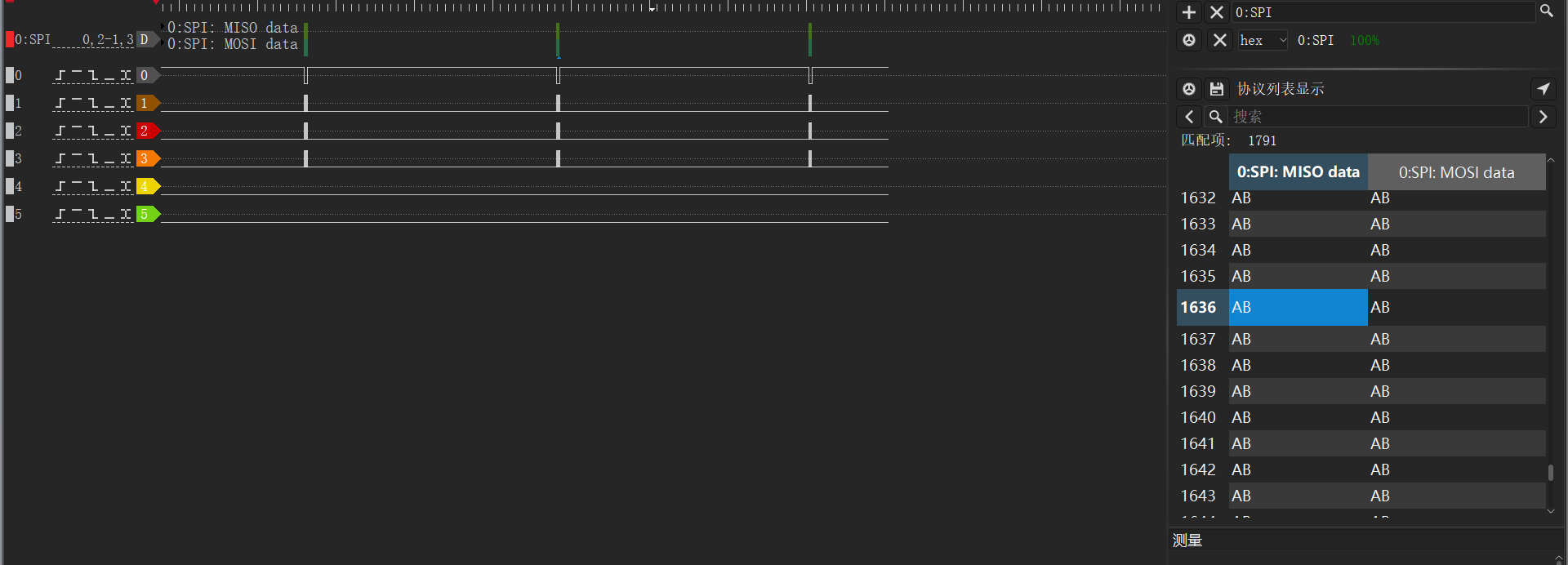
As shown in the figure above, the log prints data 0xab consistent with MOSI and MISO output, indicating successful SPI communication.
6 Common Issues
6.1 Which Protocol Does EC718’s CSPI Frame Structure Follow?
MTK protocol.
6.2 Does SPI Support MSB or LSB?
Only supports MSB.