Lierda Cellular Firmware Flashing Tool User Guide_Rev1.2
Document Revision History
Version |
Date |
Revised By |
Reviewed By |
Changes |
|---|---|---|---|---|
V1.0 |
25-12-10 |
CFT |
YMX |
Initial version |
V1.1 |
26-03-31 |
CFT |
Added project management, logging, and file system read/write features |
|
V1.2 |
27-04-05 |
ZLC |
Custom image flashing, hardware model selection, auto-update feature, English display optimization |
1. Tool Introduction
Lierda Cellular Firmware Flashing Tool is a powerful and user-friendly professional tool designed specifically for Lierda cellular communication modules. It supports core functions such as firmware compilation, application download, and full flash programming, while integrating features like project management, file system read/write, module information display, and runtime log monitoring. The tool uses PySide6 (Qt for Python) to build an intuitive graphical interface, combined with C++ core modules for high-performance operations. It is suitable for firmware development, debugging, and flashing scenarios on Windows systems, providing developers with a one-stop firmware management solution.
Key Features
Module Information Display: Supports display of basic module information, system status, network and signal information.
Multi-mode Flashing: Supports application download and full download.
Project Management: Supports management of multiple application packages, with the ability to select and compile/flash application packages directly from the project management page.
File System Read/Write: Supports read and write operations on the device file system.
Real-time Progress Monitoring: Displays operation progress and status information.
Log Recording: Supports compilation/flashing logs and module runtime logs for troubleshooting and debugging.
Log Management: Supports log save toggle, save path, size limit, and other configurations.
Automatic Device Detection: Automatically identifies serial ports in single-device scenarios; in multi-device scenarios, disconnect other devices for flashing without manual port selection.
Portable (No Installation Required): No Python environment dependency, ready to use out of the box.
Custom Image Flashing: Supports selecting custom images for firmware flashing.
Online Update: The latest version supports self-checking for update packages and completing automatic updates.
Download Address
2. System Requirements and Installation
System Requirements
Operating System: Windows 10, 11
Hardware Requirements: USB 2.0 interface, device supporting serial communication
Other Dependencies: No additional Python or runtime libraries required
Installation and Deployment
Obtain the Tool: Download the latest version archive from official Lierda channels.
Extract Files: Extract the archive to any directory (paths without Chinese characters or spaces are recommended).
Launch the Tool: Double-click the extracted executable to start.
3. Tool Interface Description
This tool is built around the core functions of module debugging, firmware flashing, and project management, with clear hierarchy and modular functionality. It covers USB/serial connection configuration, device status monitoring, real-time log viewing, firmware compilation and download, and full lifecycle management of multi-application projects. The workflow is seamless, enabling one-stop module debugging, version iteration, and product maintenance.
3.1 Main Interface
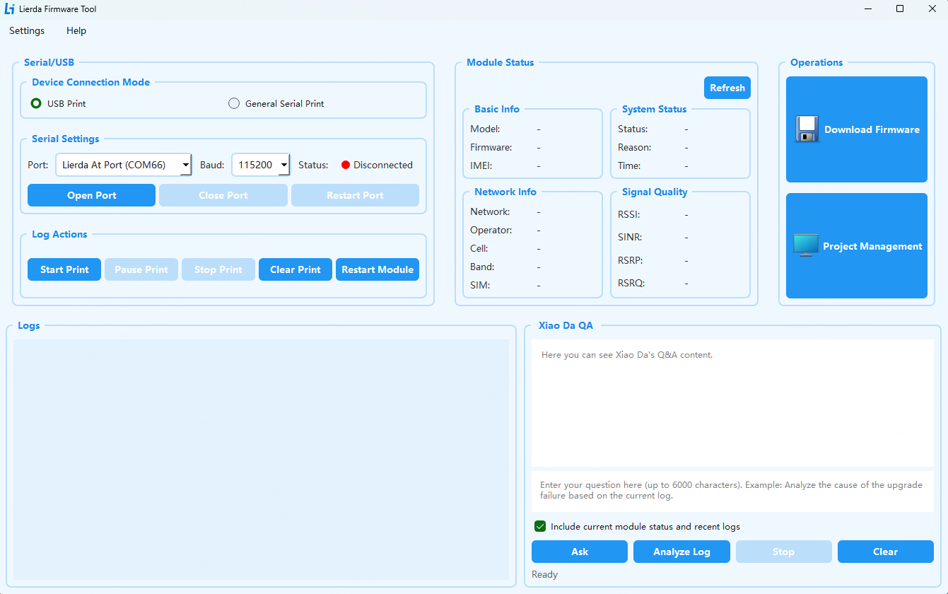
The main interface is divided into 4 core functional areas: “Serial Port / USB Configuration / Log Operation Area”, “Module Status Information Area”, “Function Operation Area”, and “Log Display Area”. Each area works independently yet collaboratively, enabling USB/serial connection, status monitoring, log viewing, firmware flashing, and project management workflows.
3.1.1 Menu Bar
Main functions include log and project management configuration.
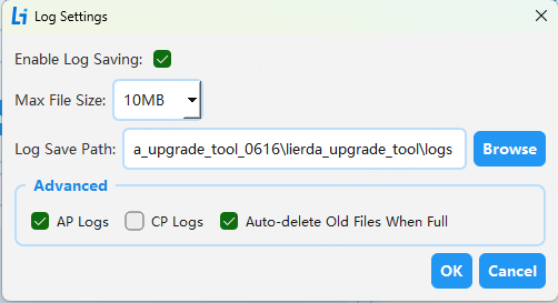
Log Configuration:
Enable Log Saving: Whether to save logs to file, enabled by default.
Log Save Path: Set the log file save location, default is under the logs path.
Log File Size Limit: Set the maximum size of a single log file, default is 10MB.
Log Advanced Options: Currently only supports AP logs, automatically deletes old files when full by default; if unchecked, all log files are preserved.
Click “OK” to save configuration.
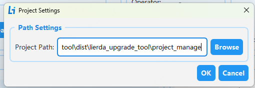
Project Management Configuration:
Project management path configuration, default is the tool’s project_manage path.
3.1.2 Serial Port / USB Configuration Area
This area is used to configure the module’s communication connection, serving as the foundation for log display, module information display, and restart operations.
Sub-module |
Description |
|---|---|
Device Connection Mode |
Two connection methods available, switch connection mode requires closing the serial port first: |
Serial Port Configuration |
Core communication parameter settings: |
Log Operations |
Module log printing and control functions: |
3.1.3 Module Status Information Area
This area displays the module’s hardware, network, and runtime status in real-time for troubleshooting and monitoring. The “Refresh” button in the upper right corner manually updates all status data.
Sub-module |
Description |
|---|---|
Basic Information |
Module core identity information (obtained via AT+LGETSTATUS? command): |
System Status |
Module runtime status (obtained via AT+LGETSTATUS? command): |
Network Information |
4G network connection details (obtained via AT+LGETSTATUS? command): |
Signal Quality |
4G signal strength key indicators (obtained via AT+LGETSTATUS? command): |
3.1.4 Function Operation Area
This area serves as the entry point for firmware download and project management functions, containing two core action buttons:
Button |
Description |
|---|---|
Download Firmware |
Core firmware flashing function: Click to enter the firmware download interface to complete firmware compilation and download, with compilation/download log and progress display. |
Project Management |
Project-level configuration management: Used to manage different APP application packages, including project creation, import, export, and supports quick compilation, flashing, and file system flashing when switching between multiple APP packages. |
3.1.5 Log Display Area
This area is the real-time log output window, displaying module runtime logs for troubleshooting and operation tracing.
3.2 Firmware Download
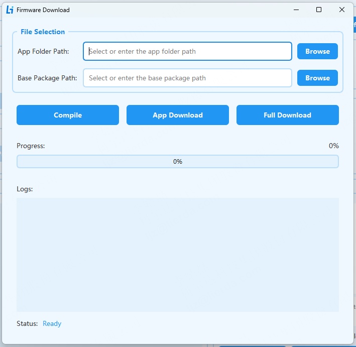
The firmware download interface contains the following areas:
File Selection Area: Used to select the application folder, base package path, hardware model, and custom image.
Action Button Area: Contains compile, application download, full download buttons.
Progress Display Area: Shows operation progress and status information.
Log Information Area: Displays operation logs and module runtime logs.
3.2.1 File Selection Area
Component |
Description |
|---|---|
Application Folder Path |
Select the SDK application package folder (e.g., SDK/examples/app). |
Base Package Path |
Select the SDK base package folder (e.g., SDK/components/basePkg/F6B_A). |
Hardware Model |
Select the current device hardware model. The tool lists supported models based on the selected base package; select according to actual hardware (e.g., NT26FCNB60WNA). |
Custom Image |
Select whether to flash a custom image. After enabling, select the custom image file path; full download will flash that image. If not enabled, the compiled image is used. |
3.2.3 Progress Display Area
Progress Bar: Shows current operation progress percentage.
Status Bar: Indicates current operation phase (e.g., “Compiling firmware…”).
3.2.4 Log Information Area
Real-time output of operation logs, including compilation and flashing operation log output.
3.3 Project Management Interface
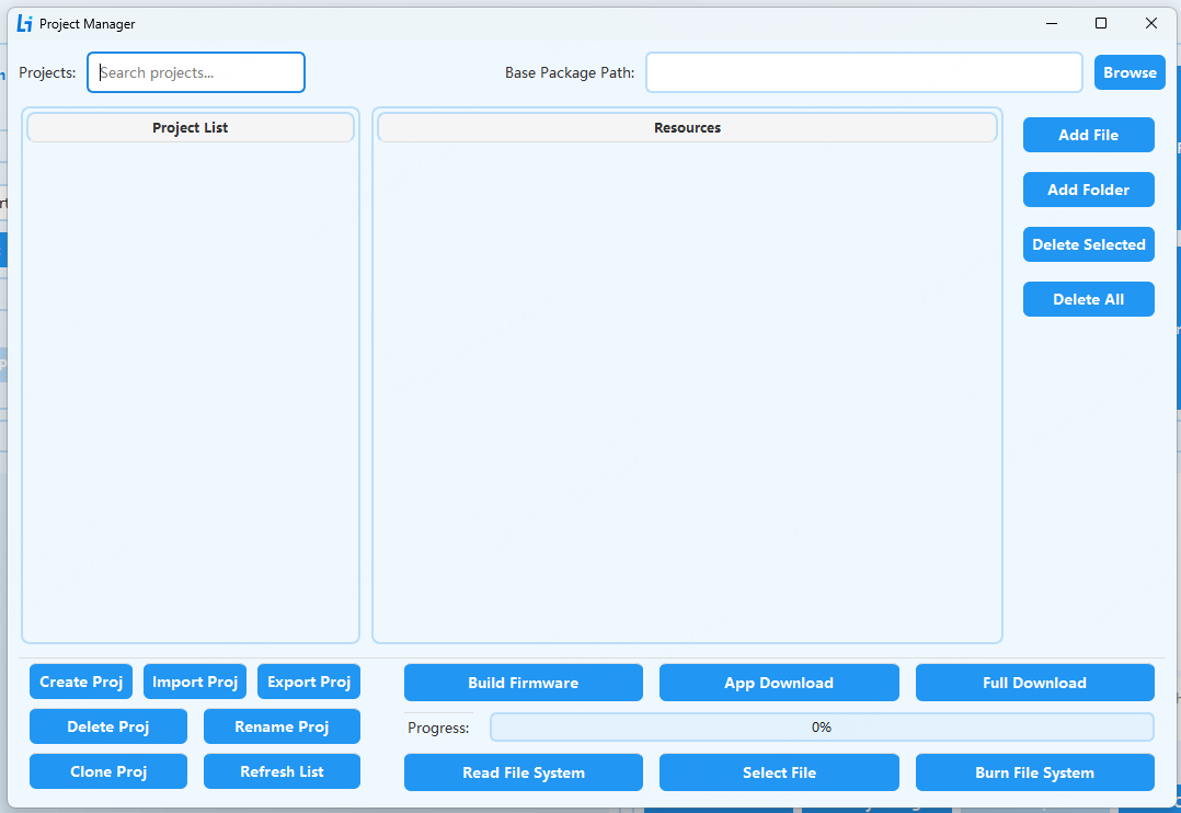
This page is the application package management and firmware compilation, flashing, and file system operation interface, supporting the full workflow of project creation, resource management, firmware generation, and flash download. It enables multi-application package management, compilation, and flashing, adapting to different product/scenario application maintenance needs.
Supports multi-application package management, allowing independent packages for different products and scenarios to avoid configuration confusion.
Enables quick project cloning, import/export, greatly improving application package management efficiency.
Integrates resource management, firmware generation, and flash execution workflow without switching interfaces.
3.3.1 Project List Area
This area is used for project search, display, and basic management, serving as the entry point for project operations.
Item / Button |
Description |
|---|---|
Search Project Input |
Supports quick keyword search by project name for efficient lookup in multi-package scenarios |
Project List |
Displays all currently created projects; selecting a project shows its resources in the right panel |
Create Project |
Create a new blank project for new development |
Import Project |
Import an existing external project to quickly reuse historical project code |
Export Project |
Export the currently selected project for backup |
Delete Project |
Delete the selected project to free up project list space |
Rename Project |
Modify the selected project’s name for classification and version iteration needs |
Clone Project |
Copy the complete code of the selected project to generate a new clone for quickly creating similar projects |
Refresh List |
Refresh the project list to sync the latest project creation/modification status |
3.3.2 Resource Configuration Area
This area is used for project resource file management and flashing configuration, serving as the core configuration carrier.
Item / Button |
Description |
|---|---|
Base Package Path Input |
Configure the base package file path for the project |
Select Path Button |
Click to open file browser for quick base package path selection |
Resource List |
Displays all resource files/directories of the currently selected project |
Add File |
Add a single file to the current project’s resource list |
Add Directory |
Add an entire directory to the resource list for batch import |
Delete Selected |
Delete selected files/directories from the resource list |
Delete All |
Clear all resource list contents of the current project |
3.3.3 Firmware Generation and Flashing Operation Area
This area is the core business operation entry for firmware generation and module flashing.
Button |
Description |
|---|---|
Generate Firmware |
Package and generate a complete flashable firmware based on current project configuration and resources |
Application Download |
Flash only the application firmware to the device, partial Flash erase/write (does not affect base package configuration). |
Full Download |
Flash both application and base package firmware to the device, full Flash format and rewrite. |
Progress Bar |
Real-time display of flashing/firmware generation progress for intuitive status feedback. |
Read File System |
Read the module’s current file system contents. (Via fs_read.bat script in the built-in flasher_tool, configuring parameters and calling FlashToolCLI.exe) |
Select File |
Select the target file for flashing |
Flash File System |
Flash the selected file to the module to update the module’s file system. (Via fs_fileadd_and_fs_flashwrite.bat script in the built-in flasher_tool, configuring parameters and calling FlashToolCLI.exe) |
3.4 Auto Update
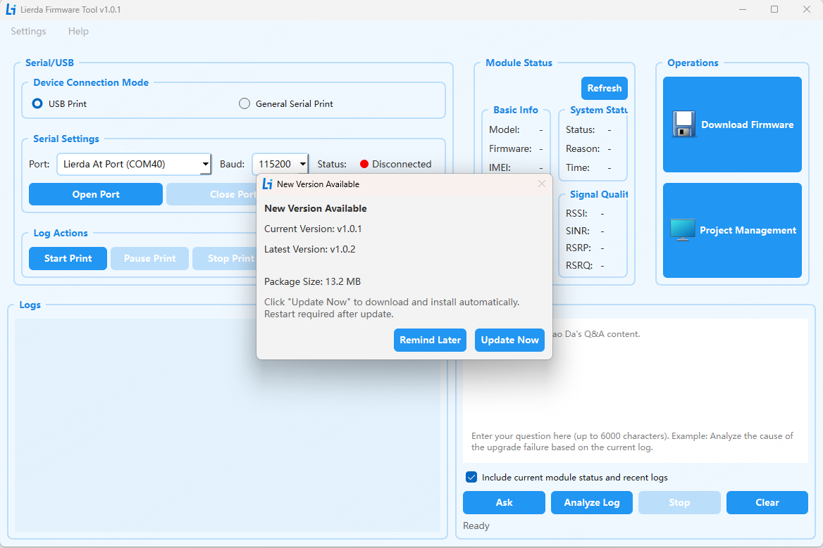
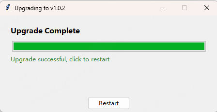
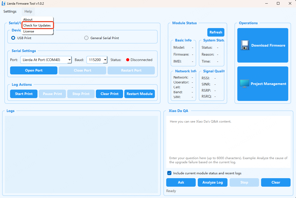
There are 2 update methods: automatic detection and manual detection.
On startup, the tool automatically checks for update packages. If a newer version is available, the user is prompted whether to upgrade.
4. Detailed Operation Steps
Step 1: Preparation
Device Connection:
Connect the target module to the computer using a USB cable and power on the module.
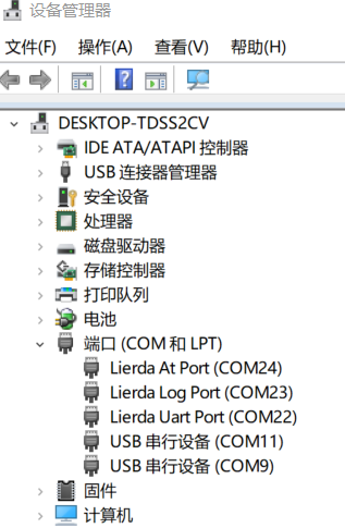
Ensure the module driver is installed. The following port recognition in Device Manager indicates successful driver installation.
SDK Package Preparation:
Confirm the SDK package is complete, containing the application code folder, build.bat compilation script, and base package files (.binpkg format), and that files have not been quarantined or modified by antivirus software.
4.1 Log Printing and Module Information Display
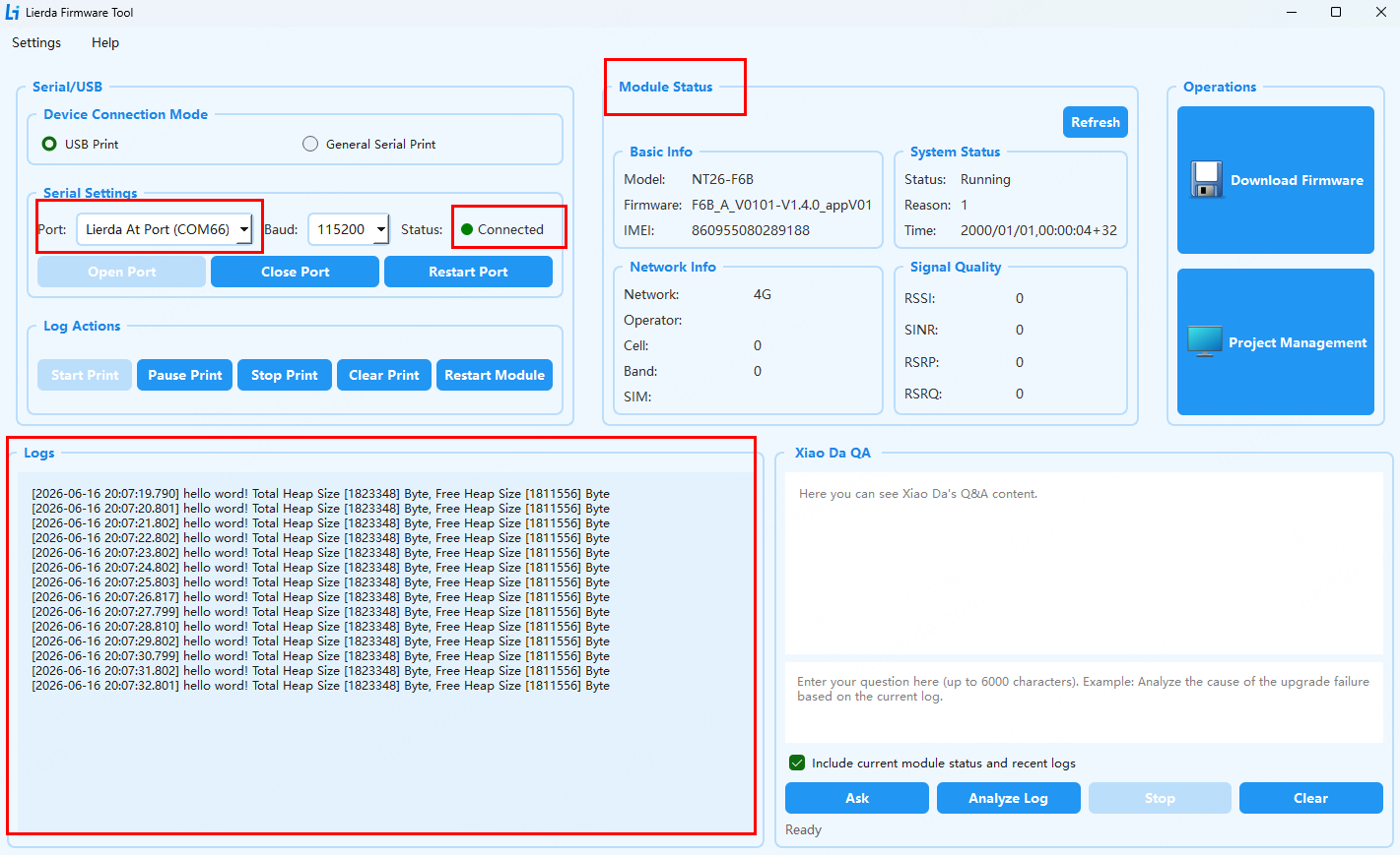
The SDK outputs logs via USB port by default. Select the Lierda At Port and open the serial port. Once the device connection status shows “Connected”, the tool automatically obtains module information via the AT+LGETSTATUS? command and updates the interface. To restart the module, simply click the button. Logs are saved to the tool’s logs path by default. After selecting “Start Print”, the interface displays module runtime logs as follows:
4.2 Firmware Compilation and Flashing
Before compiling, ensure the Python environment has been installed according to the Quick Start Guide.
Step 1: Compilation File Selection
Application Folder:
Click the “Browse” button and select the target application package under the /SDK/examples path.
Base Package File:
Click the “Browse” button and select the target base package under the SDK/components/basePkg path.
Hardware Model:
Select the target hardware model. Different base packages may correspond to multiple hardware models; select according to actual hardware. Here we select NT26FCNB60WNA.
Step 2: Execute Operation
Click the “Compile” button, the tool will perform the following:
Execute
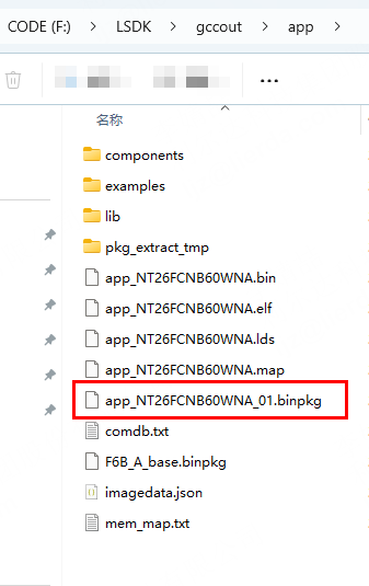
build.bat all PROJECT=app MODEMPKG=F6B_A MODEM=NT26FCNB60WNAcommand to compile firmware, where PROJECT is the selected application package name and MODEMPKG is the base package name.After successful compilation, the target file with .binpkg suffix starting with {app package name} is generated under the
SDK/gccout/{app package}path.
Result Notification:
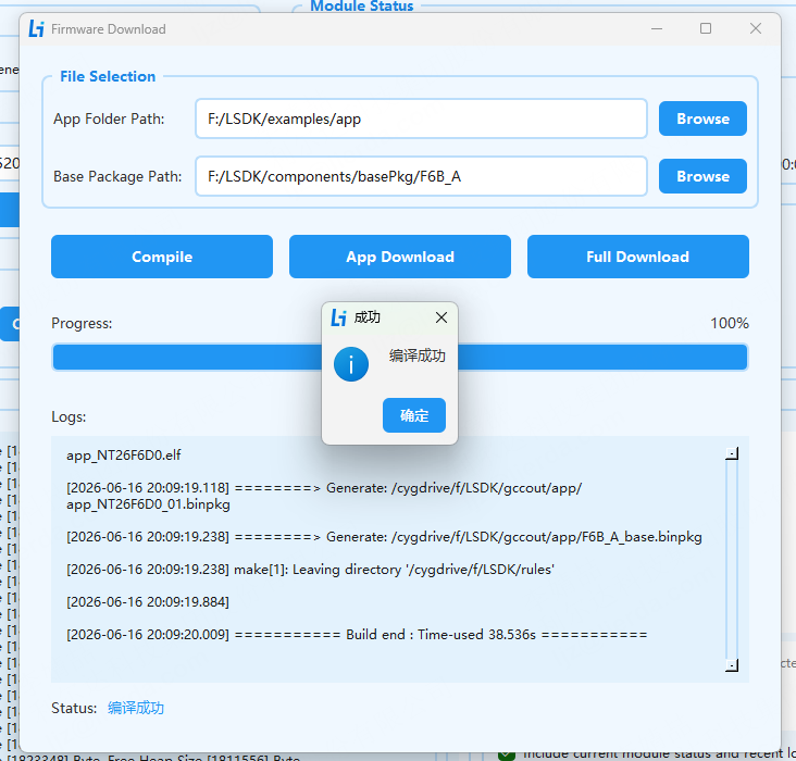
Compilation successful: Log displays “Compilation successful”.
Compilation failed: Check code structure or dependency environment, refer to logs and tool status prompts to locate errors.
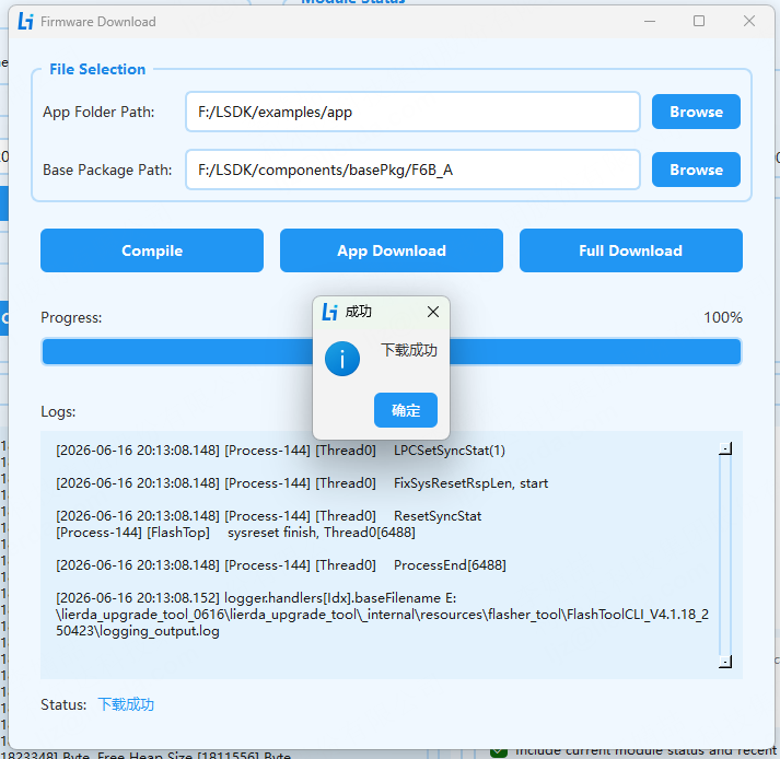
Step 3: Execute Application Download
If the device has normally enumerated the USB AT port, the tool will automatically send a command to enter boot mode. If the device has not enumerated, ensure the device has entered download mode or switch to download mode immediately after clicking download. To enter download mode: After powering on the device, pull the BOOT pin high and reset the module. The Lierda QDLoader Port is the download port.

Click the “Application Download” button, the tool will:
Automatically detect the download port based on PID/VID.
Call the
FlashToolCLItool to flash the application firmware.Automatically restart the device after download completes.
Step 4: Execute Full Download
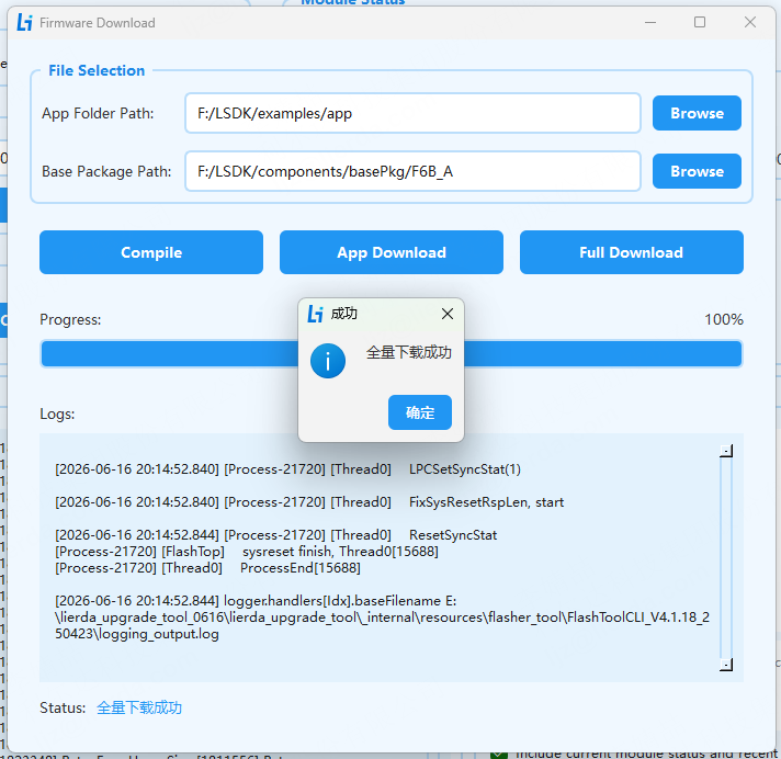
If the device has normally enumerated the USB AT port, the tool will automatically send a command to enter boot mode. If the device has not enumerated, ensure the device has entered download mode or switch to download mode immediately after clicking download.
Click the “Full Download” button, the tool will:
Automatically detect the download port based on PID/VID.
Call the
FlashToolCLItool to flash the firmware.Automatically restart the device after download completes.
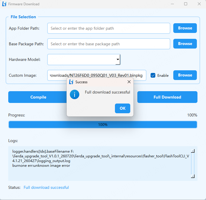
Custom Image Flashing
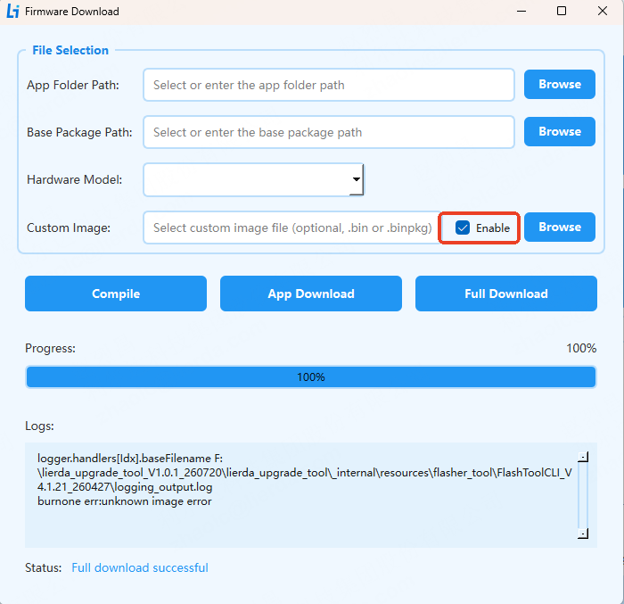
The tool supports selecting non-compiled images for flashing by enabling the custom image option and selecting the custom image.
⚠️ Note:
  1. When custom image is not enabled, the compiled image is flashed.
  2. When custom image is enabled, the image from the custom path is flashed, and only full download is supported.
Steps are as follows:
Step 1: Enable Custom Image
Step 2: Select Custom Image Click the Browse button to select the custom image path. The image name must end with binpkg.
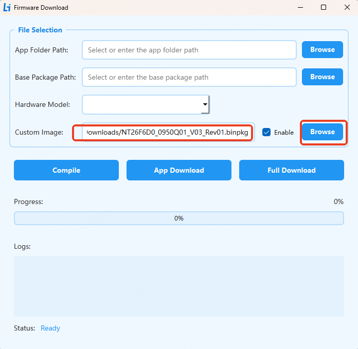
Step 3: Execute Full Download Click Full Download to flash. If the device has normally enumerated the USB AT port, the tool will automatically send a command to enter boot mode. If the device has not enumerated, ensure the device has entered download mode or switch to download mode immediately after clicking download.
4.3 Project Management
The default project management path is project_manage under the tool’s root path. The default path can be modified in the menu bar project management configuration page.
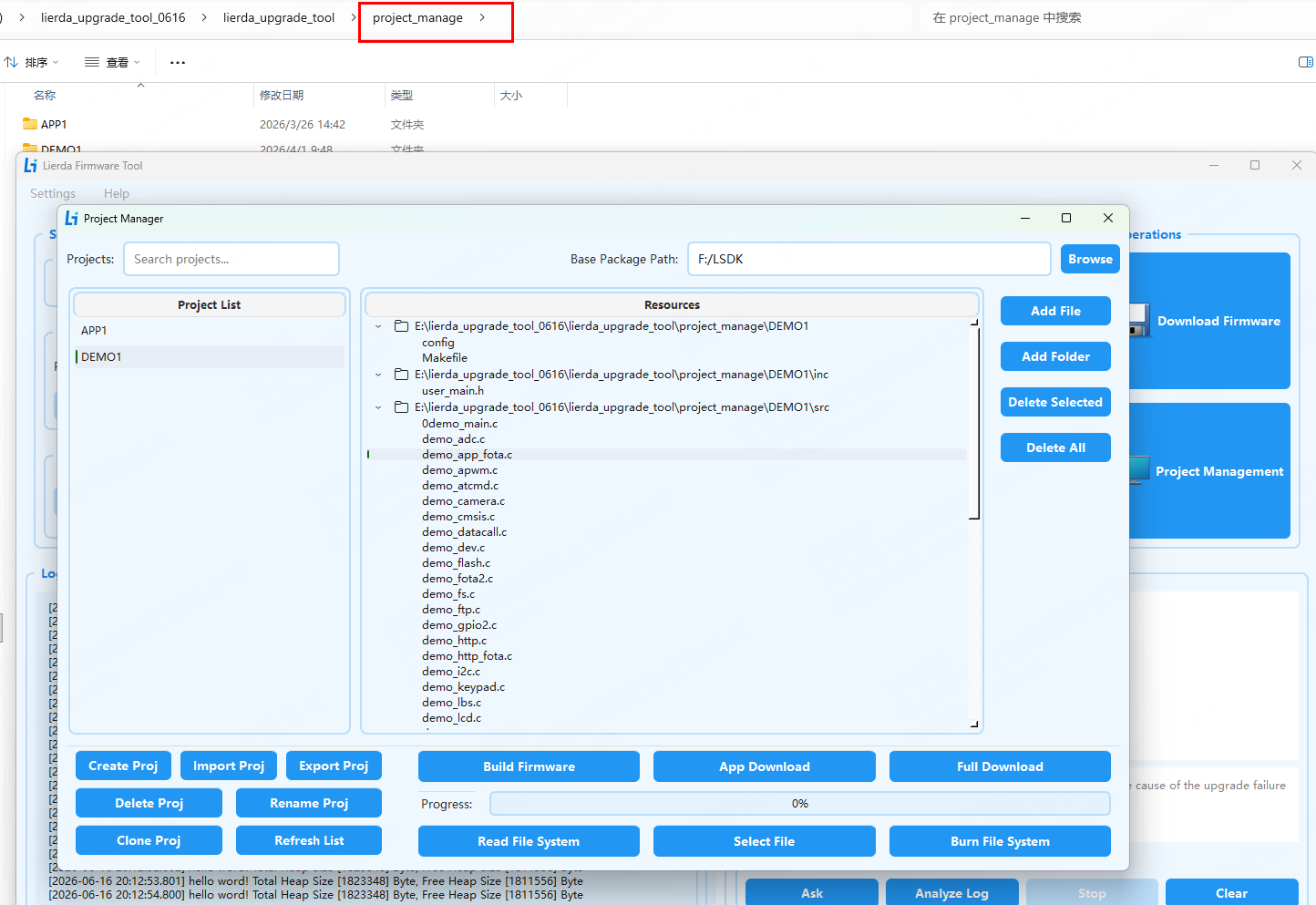
4.3.1 Project Management
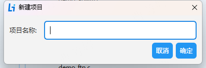
Create Project:
Click the “Create Project” button.
Enter the project name and add files/directories to the project using the buttons on the right.
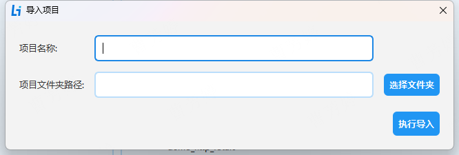
Import Project:
Enter the project name.
Select the project folder path to complete the import.
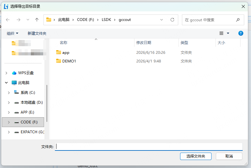
Export Project:
Select the project folder export path to complete the export.
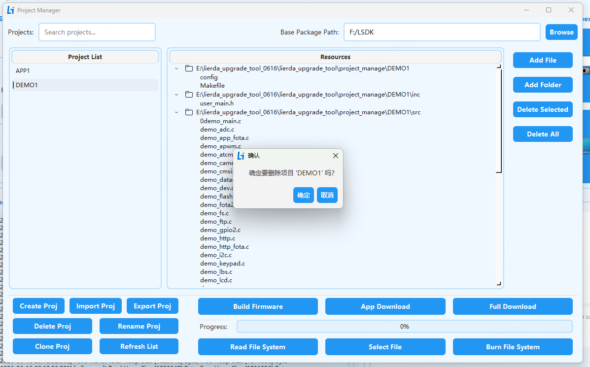
Delete Project:
Select the project to delete.
Click the “Delete Project” button to complete the deletion.
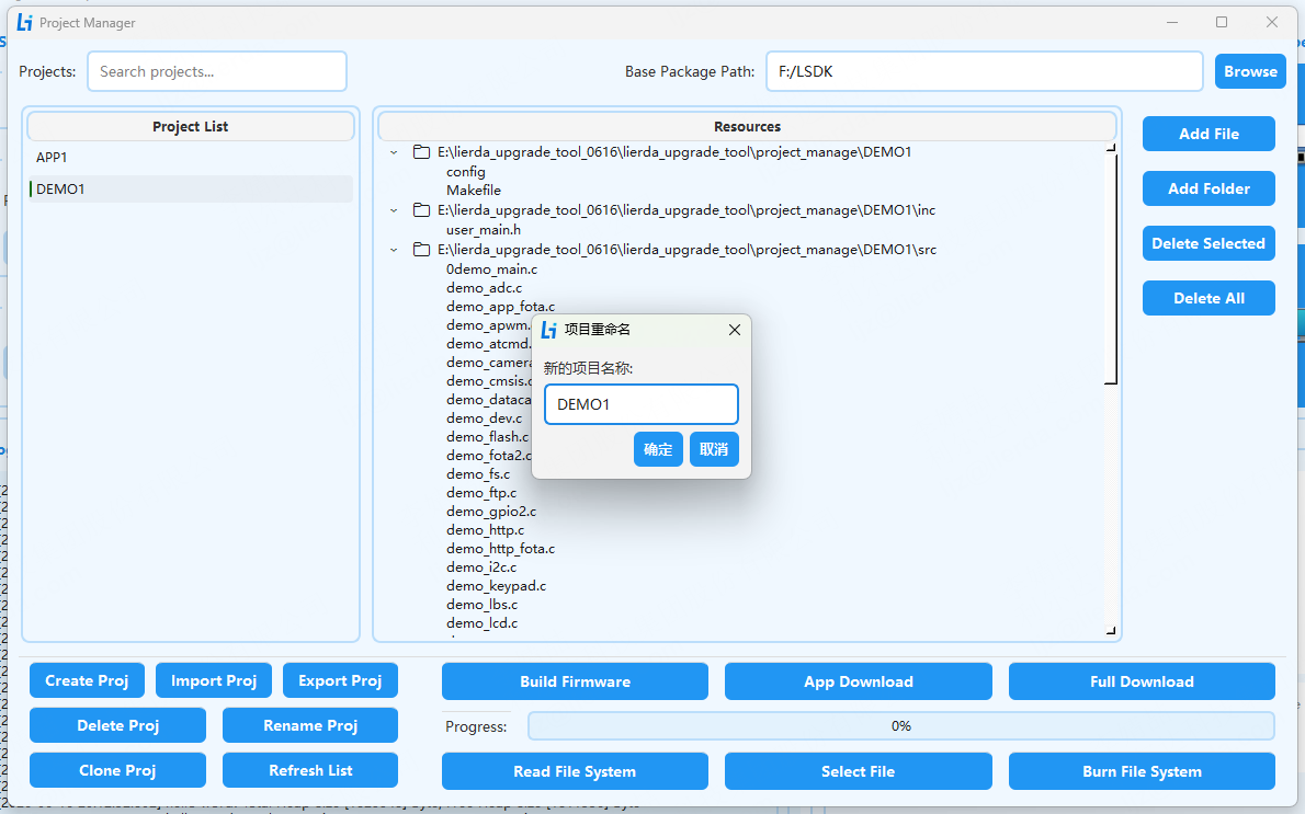
Rename Project:
Select the project to rename.
Enter the new project name to complete the rename.
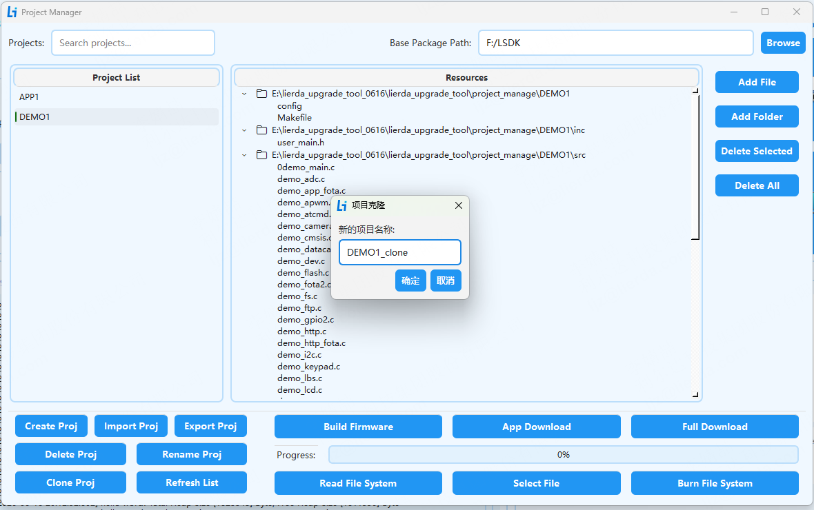
Clone Project:
Select the project to clone.
Enter the new cloned project name to complete the clone.
Refresh List:
Click the button to refresh the project list.
4.3.2 Firmware Compilation and Flashing in Project Management
On this page, compilation and firmware flashing require selecting an application package from the left panel and selecting the base package in the upper right corner before compiling/flashing. Compilation must be performed before application download or full download, because the corresponding application package is only copied to the SDK app package path during the compilation phase. Compilation and flashing operation logs are not displayed on this page; only progress and operation result pop-up notifications are shown. The specific operations are consistent with the firmware download page and will not be repeated here.
4.3.3 File System Read/Write
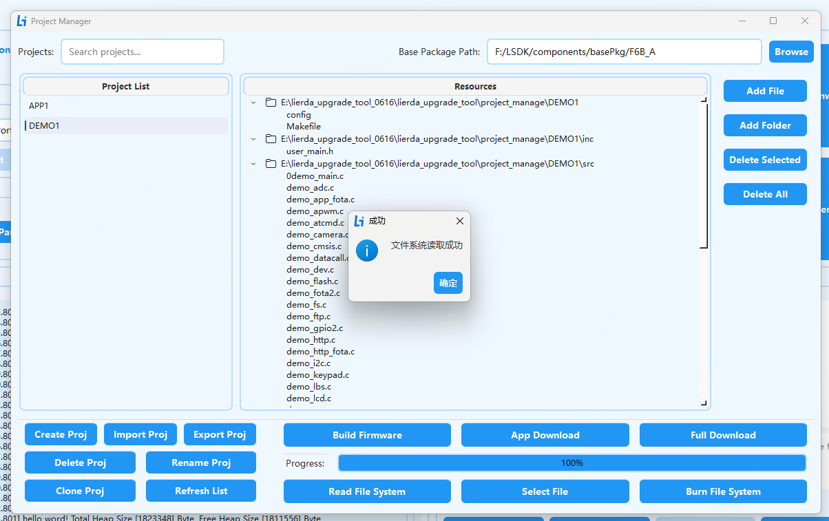
File system read/write requires selecting an application package from the left panel and selecting the base package in the upper right corner. The tool determines the output path through the application package name and finds the partion_info.txt file through the base package path to confirm the start address and length for reading the file system.
File system read/write follows the same process as flashing and requires switching to the download port. See above for how to switch to download mode.
Read File System Ensure the device is in flashing mode.
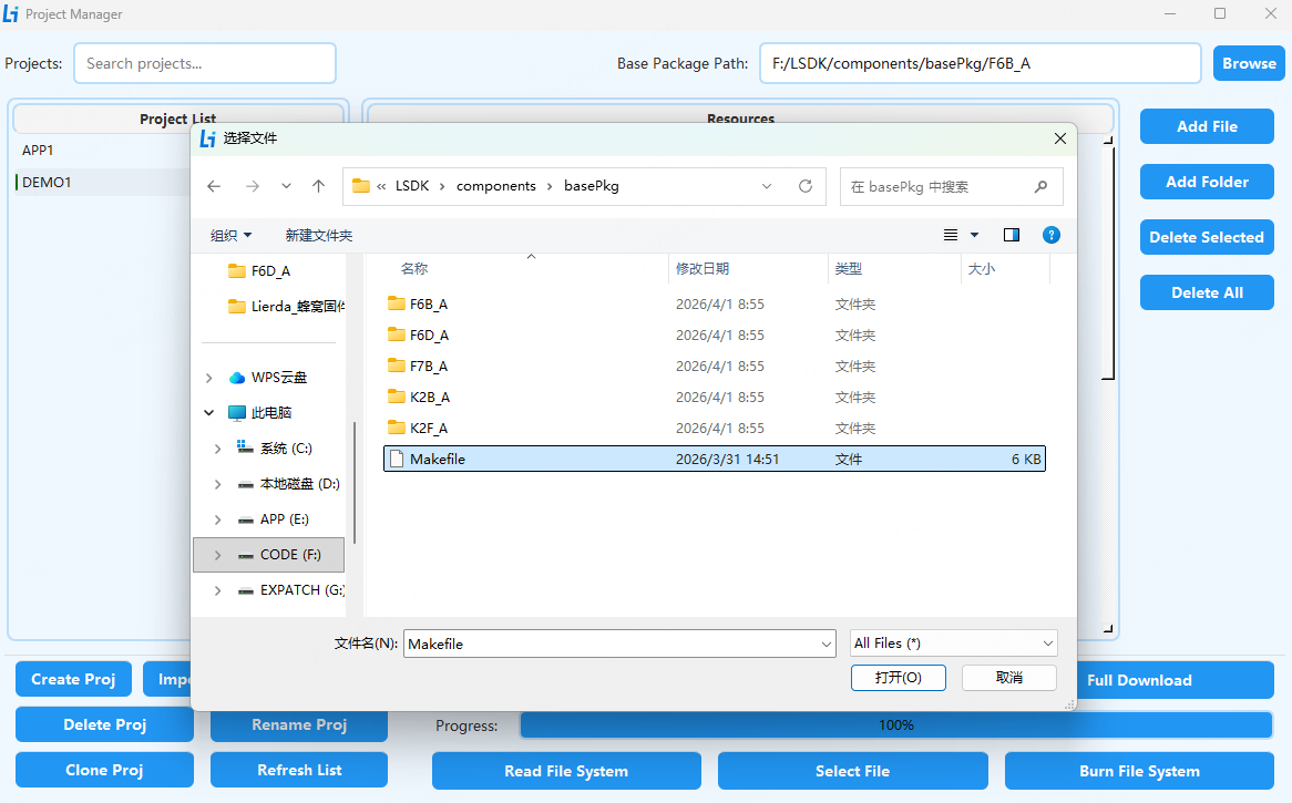
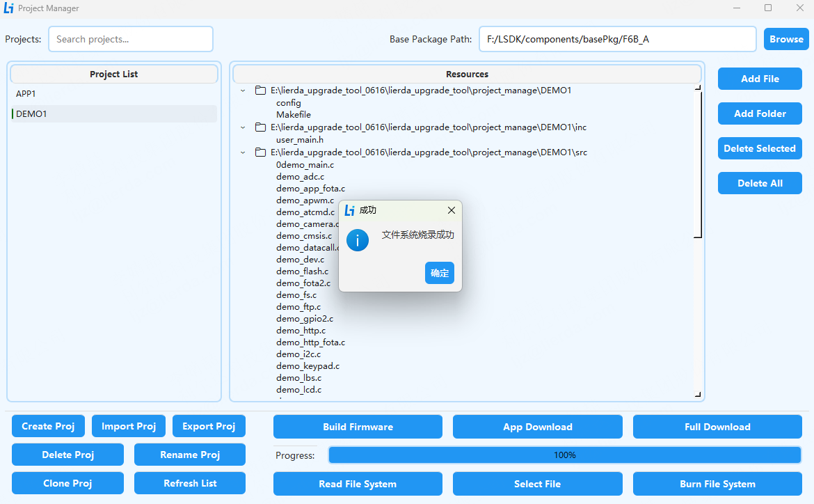
Write File System Select the file to flash, then click the “Flash File System” button. Also ensure the device is in flashing mode.
5. Notes and FAQ
Important Notes
File Paths: Ensure paths do not contain Chinese characters, spaces, or special characters.
Device Status: After installing the driver, ensure the device is properly recognized. Before downloading or after clicking the download button, manually switch the device to download mode; otherwise, flashing may fail.
During Flashing: Never disconnect power or remove the USB cable during the flashing process, as this may corrupt the module firmware and prevent startup.
File System Operations: Ensure the device is in flashing mode during file system read/write operations.
Log Configuration: Ensure the log file path has write permissions to avoid log saving failures due to permission issues.