Lierda Cat.1 NT26FxDx OpenKit Lite Version Quick Start Guide Rev1.0
Document Revision History
Version |
Date |
Author |
Reviewer |
Revision |
|---|---|---|---|---|
Rev1.0 |
2026-05-20 |
zxq |
zlc |
Initial release |
1 Introduction
This document introduces the basic information of the 01_V04 hardware, including how to get started, install drivers, download firmware, and run a demo, helping users quickly become familiar with the hardware and software environment.
1.1 Preparation
Hardware checklist
Item |
Description |
|---|---|
Development board |
NT26FxDx OpenKit Lite development board |
SIM card |
Activated 4G SIM card. Required for network functions, not required for lighting up the RGB LED |
USB cable |
Type-C data cable for connecting the PC and development board |
PC |
Windows 10/11 |
Software checklist
Item |
Description |
|---|---|
SDK source code |
|
Code editor |
Visual Studio Code or any text editor, used to view and modify source code |
USB driver |
Download LierdaCommonUSBSetup_V3.4.6.exe. After installation, Lierda ports will appear in Device Manager. For installation steps, refer to USB Driver Installation Guide |
Lierda Tools flashing tool |
Download lierda_upgrade_tool_latest.zip. This tool integrates build and flashing functions. For usage, refer to Lierda Cellular Firmware Flashing Tool User Guide Rev1.0 |
Tip: When building with Lierda Tools, you do not need to install GCC or configure the build environment separately. The tool includes the complete toolchain.
2 Getting to Know the Development Board
2.1 Hardware Features Overview
Before getting started, it is important to understand some basic product parameters. The table below provides feature information for the NT26-EC718PM AI development board.
Please refer to NT26FxDx OpenKit Application Guide Rev0.1
3 PC Driver Installation
The USB driver is the bridge between the PC and the development board. During development, firmware flashing, AT command sending, and log capture all require USB, so installing the USB driver is a prerequisite for development work.
Refer to the document Lierda LTE-EC71x OpenCPU USB Driver Installation Guide for driver installation. After the driver is correctly installed and the board is powered on, the following three COM ports will appear.
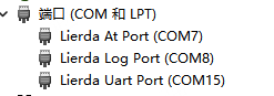
The two commonly used COM ports are:
Lierda AT Port: used for sending AT commands, firmware download, and AT command communication.
Lierda Log Port: used for capturing logs. This port is used when capturing logs with the EPAT tool.
4 Flashing Tool and Log Tool
4.1 Flashing Tool
4.2 Log Tool
5 How to Power On
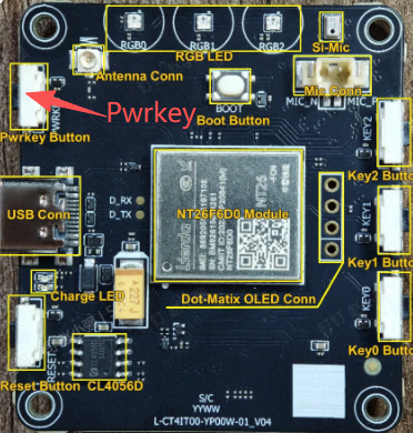
In general, inserting the USB cable will power on the board automatically. If the board does not power on and no COM ports appear, use the PWRKEY button.
PWRKEY operation: short press for 500 ms to power on, long press for 650 ms to power off.
The PWRKEY is located on Side A of the board, as shown below:
6 Getting the SDK
The SDK is available at:
https://github.com/lierda-iot/CAT1.bis_OpenCPU
6.1 Installing Git on Windows
In a Windows environment, install Git for Windows first. After installation, you can use git clone to obtain the SDK source code.
Open the Git for Windows website: https://gitforwindows.org/.
Click Download to download the installer, then double-click it to install.
If there are no special requirements, keep the default options. It is recommended to keep
Git Bash Hereand the option that adds Git to the system environment variables, so Git can be used from the command line.After installation, open Windows Command Prompt, PowerShell, or Git Bash, and run the following command to verify the installation:
git --version
If the Git version is displayed, Git has been installed successfully.
After Git is installed, open Git Bash or a command line window in the directory where you want to save the SDK, and run:
git clone https://github.com/lierda-iot/CAT1.bis_OpenCPU.git
For a detailed introduction to the SDK, refer to the following document:
7 Configure and Build the RGB LED Demo
7.1 Confirm the Module Model
Check the marking on the module shield to confirm the module model used by the development board.
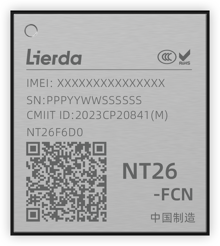
For example, if the marking is NT26F6D0, the corresponding base package is F6D_A. The currently supported versions and models are listed below. For the latest mapping, refer to rules/Makefile.modem in the SDK.
Base package |
Chip model |
Applicable module |
Description |
|---|---|---|---|
F6C_A |
EC718PM |
NT26F6C0 |
C series general version |
F6D_A |
EC718PM |
NT26F6D0, NT26F6D0_EU, NT26F6D0_LA, NT26F6D0_NA |
D series general version |
F6D_GL |
EC718PM |
NT26F6D0_GL |
D series global version |
K2B_A |
EC716E |
NT26K2B1, NT26K2B3 |
B series, full OTA is not supported |
K2E_A |
EC716E |
NT26K2E0 |
E series, full OTA is not supported |
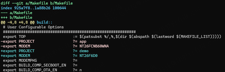
The module model and base package name will be used when modifying the Makefile. For example: module model = NT26F6D0, base package = F6D_A.
7.2 Modify the Makefile
Open the Makefile in the SDK root directory, and modify the project, module, and base package configuration according to the module model and base package confirmed in the previous step.
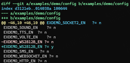
7.3 Modify examples/L_CT4IT00_YP00W_01_V04/config
This file controls which demo is compiled. For example, to compile the RGB LED demo, select it here. You can also choose other demos as needed through macro configuration.
7.4 Build
Method 1: Build with Lierda Tools (recommended)
Open Lierda Tools.
For “Application folder path”, click Browse and select
examples/L_CT4IT00_YP00W_01_V04under the SDK root directory.For “Base package path”, click Browse and select
components/basePkg/F6D_Aunder the SDK root directory. If you are using another module, select the base package directory that matches the result confirmed in Section 7.1.Click Build and wait for the build success prompt.
Method 2: Build from the command line
Go to the SDK root directory and run make all. If the build completes successfully, the following output will appear.

8 Flash and Verify
8.1 Enter Download Mode
Before flashing, the module must enter download mode. Use either of the following methods:
Method 1: Hold down the BOOT button on the development board, press the RESET button or replug USB, and then release BOOT.
Method 2: Click Full Download in Lierda Tools. When the tool prompts you to enter download mode, perform the BOOT and RESET operation described above.
8.2 Full Download
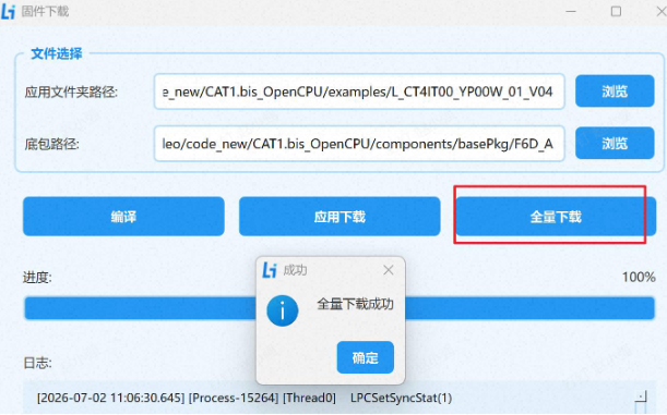
After the build is complete, select the firmware file gccout/L_CT4IT00_YP00W_01_V04/L_CT4IT00_YP00W_01_V04_NT26F6D0_01.binpkg for flashing.
Configure the flashing tool as shown below. Pay attention to the base package path and application folder path. After confirming that the Lierda download port is visible in Device Manager, click Full Download. The tool will automatically detect the port, flash the firmware, and restart the device after completion.
9 Check the Running Result
9.1 Observe the RGB LED
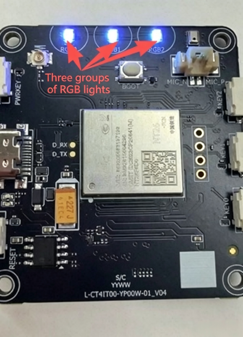
After flashing, the device restarts automatically. If everything is normal, the RGB LED will keep cycling through colors, indicating that the build and flashing were successful.
9.2 Check Serial Logs
To confirm that the program is running, you can check the serial log output:
Open Lierda Tools.
Select the COM port corresponding to
Lierda At Port.Set the baud rate to
115200.Click Start Print.
After the program starts, the serial port prints content similar to the following. The values vary depending on the actual memory status.
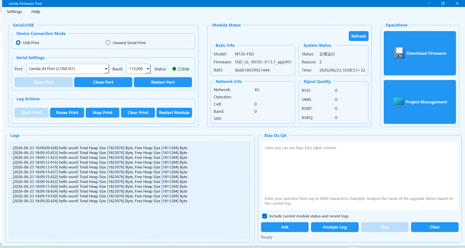
hello word! Total Heap Size [xxxxx] Byte, Free Heap Size [xxxxx] Byte
When this log appears, the program is running successfully.