OpenKit Application Guide_Rev0.2
Please remove the enclosure and check the silkscreen model and version on the main board to confirm that your development board version matches this application guide.
NT26FxDx OpenKit is an embedded development kit based on a Cat.1 communication module for rapid evaluation and development with Lierda’s NT26F series OpenCPU SDK. The kit integrates cellular networking, voice interaction, a camera, touch screen, LCD display, and peripheral expansion, helping customers quickly become familiar with module capabilities and carry out application validation.
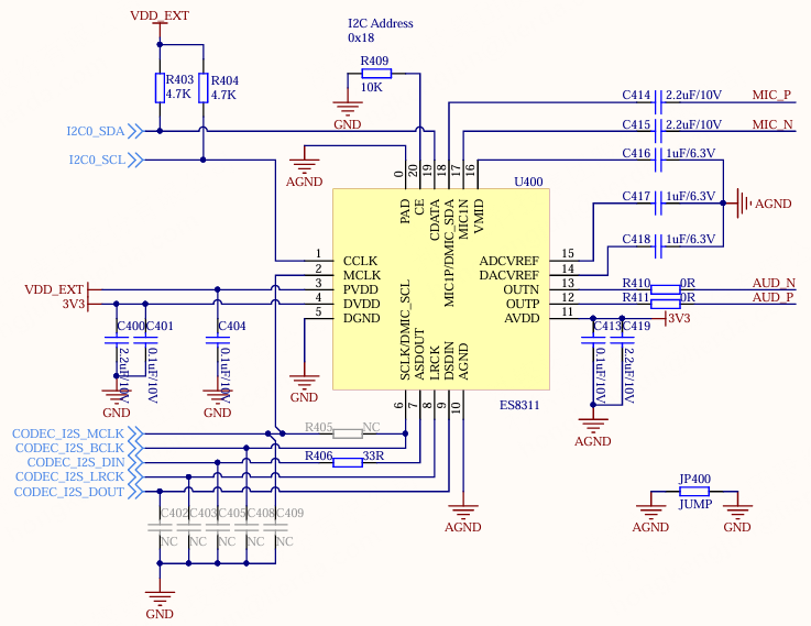
The development board includes an NT26FxDx module, onboard ES8311 audio codec, Class-AB/Class-D power amplifier, camera interface, and LCD/dot-matrix display interfaces, while also integrating lithium battery charging management and multiple regulated power supply circuits. Based on this kit, users can implement network communication, voice capture and playback, screen display, image acquisition, and other functions. It is suitable for prototype development and functional validation in scenarios such as smart terminals, voice interaction, image acquisition, and IoT devices.
This application guide will help you get started quickly with NT26FxDx OpenKit and provide detailed information about this development board.
TBD
This guide includes the following content:
Hardware Version: Introduces hardware revision history and known issues.
Getting Started: Briefly introduces the development board and provides hardware and software setup guidance.
Hardware Reference: Provides detailed hardware information for the development board.
Related Resources: Lists links to related documents.
Hardware Version
This document applies only to the NT26FxDx OpenKit main board model: L-CT4IT00-YP00W-01_V04.
PCB Model |
PCB Version |
Change Log |
|---|---|---|
L-CT4IT00-YP00W-01 |
V04 |
/ |
Getting Started
This section briefly introduces NT26FxDx OpenKit and explains how to flash firmware onto NT26FxDx OpenKit and prepare the required environment.
Component Introduction
Component Model |
Description |
|---|---|
L-CT4IT00-YP00W-01_V04 |
Main Board PCB |
24031C12 |
LCD+TP |
ZJY096I0400WG01 |
OLED |
TBD |
Battery |
TBD |
Enclosure |
TBD |
Camera |
TBD |
LCD ADP PCB |
TBD |
Speaker |
TBD |
Antenna |
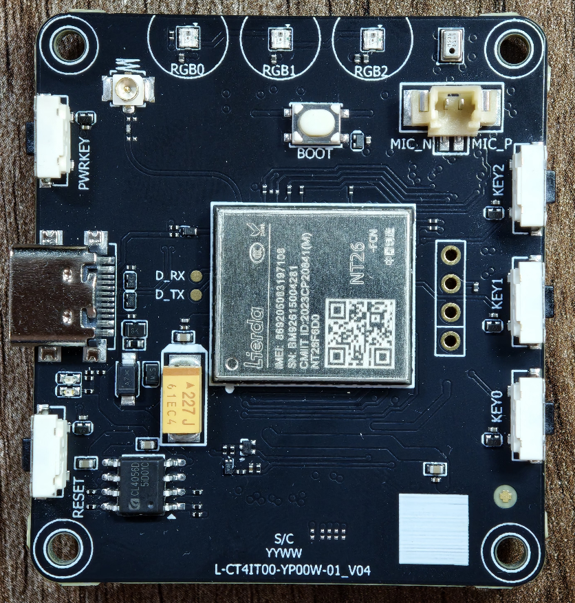
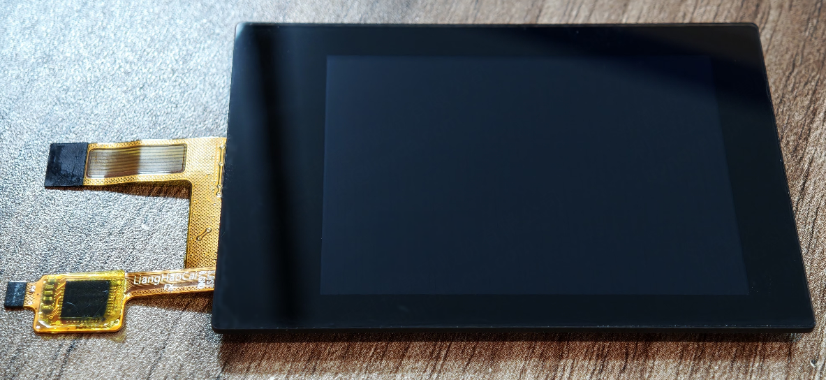
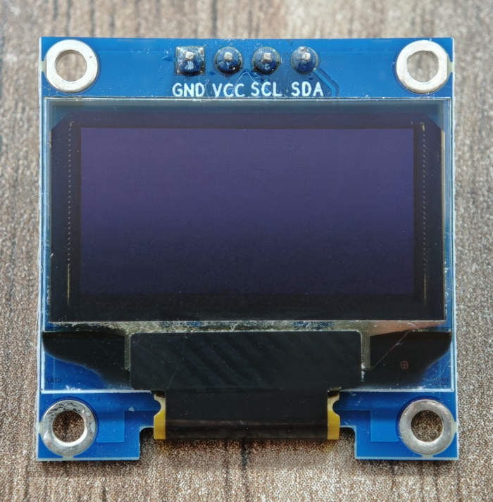
TBD (Enclosure)
TBD (Battery)
TBD (Camera)
TBD (LCD ADP PCB)
TBD (Speaker)
TBD (Antenna)
Main Board Introduction
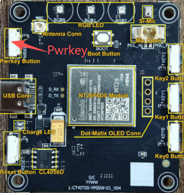
The main components and interfaces of NT26FxDx OpenKit are described below:
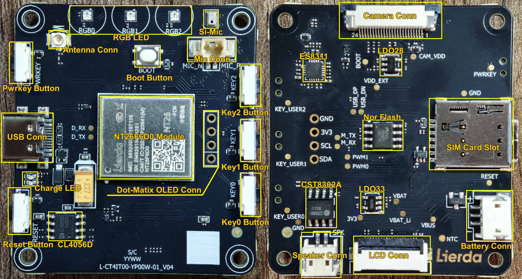
Main Components (TOP) |
Description |
|---|---|
Pwrkey Button |
Pwrkey, used to power the module on and off |
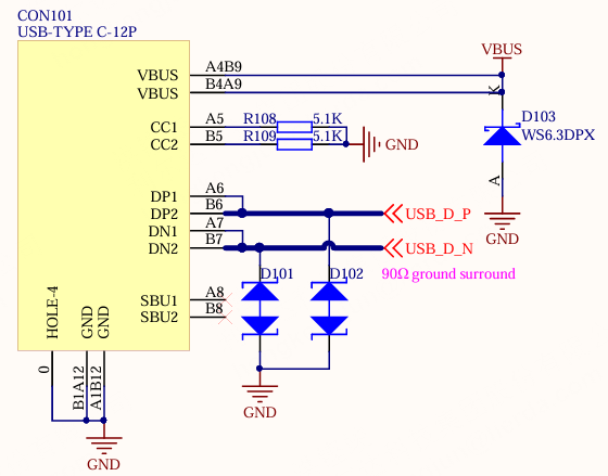
USB Connector*(1)* |
Type-C connector for power supply, charging, communication, and download |
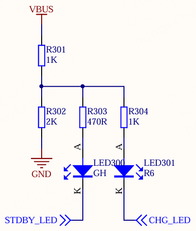
Charging Indicator |
Two indicators, red and green. The red light stays on while charging, and the green light stays on when fully charged |
Reset Button |
Reset, used to reset the module |
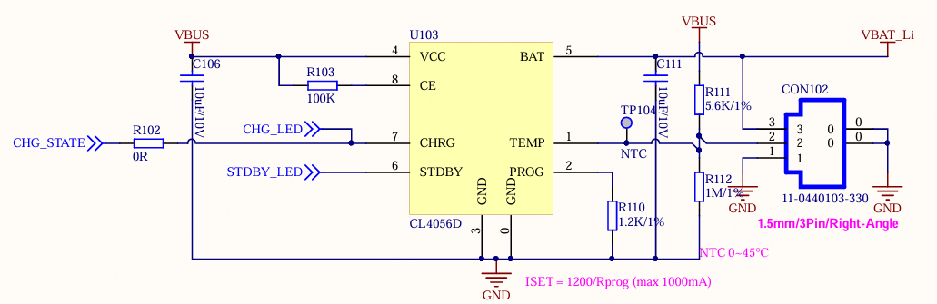
CL4056D |
Charging management chip, suitable for 4.2V batteries |
Antenna Socket |
IPEX Gen-1 socket |
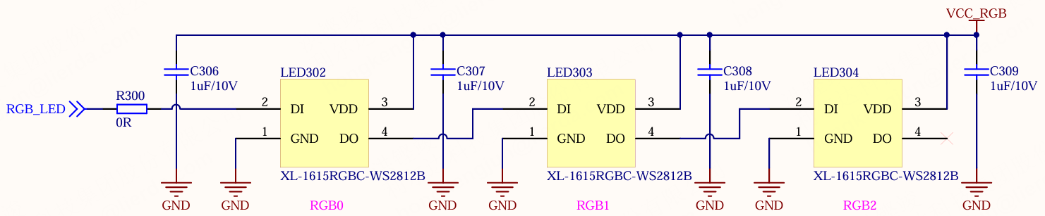
RGB LED |
RGB indicator, indicates module operating status |
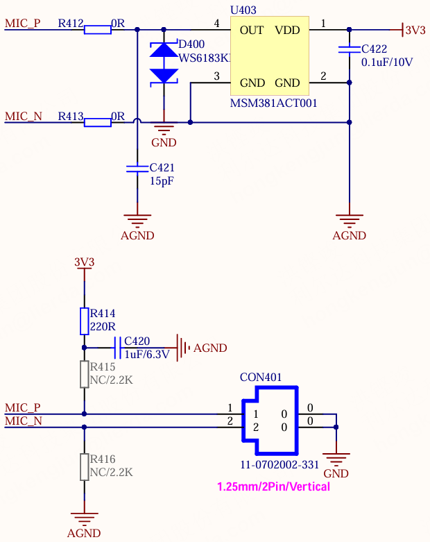
Onboard Silicon MIC |
Either this or the microphone connector can be used |
Microphone Connector*(2)* |
1.25mm/2PIN connector socket for connecting an electret microphone |
Boot Button |
Used to force entry into download mode |
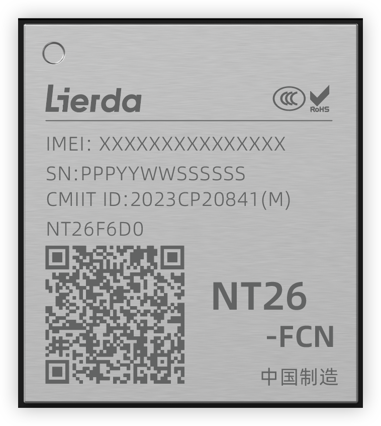
NT26F6D0 Module |
Cat.1 bis module supporting OPEN application development |
Dot-Matrix Display Connector |
Used to connect an SSD1306 dot-matrix display (12864/12832) |
Key0/1/2 Buttons |
Three user-defined buttons |
Main Components (BOT) |
Description |
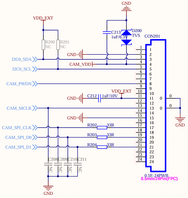
Camera Connector*(3)* |
0.5mm/24PIN FPC connector for connecting a camera module |
ES8311 |
High-performance audio codec chip |
LDO28 |
2.8V/300mA low-dropout linear regulator |
Nor flash |
Nor flash chip, 32Mbit, suitable for 3.3V systems |
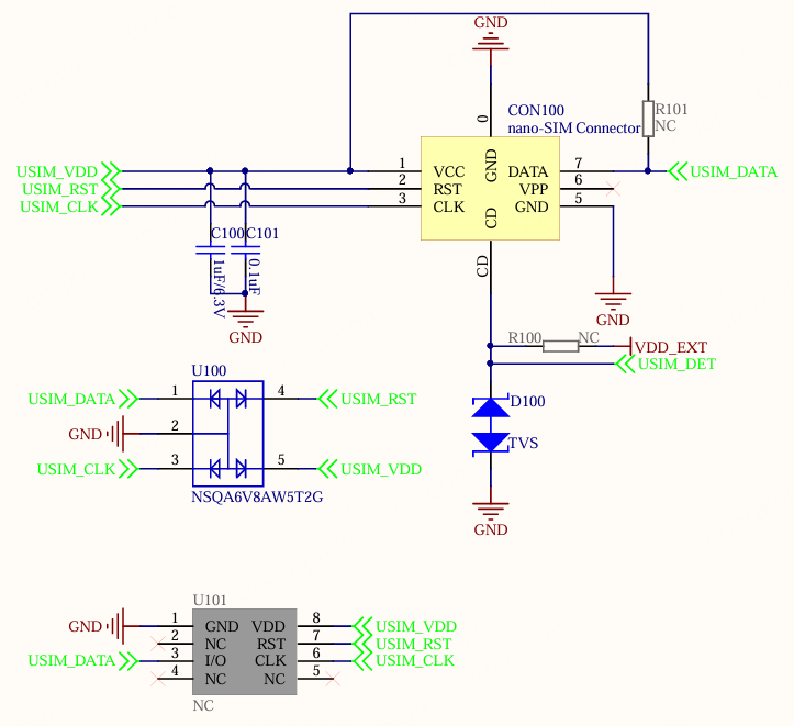
SIM Card Slot |
Nano-SIM card slot connector for inserting a SIM card |
CST8302A |
Class-AB/Class-D amplifier |
LDO33 |
3.3V/300mA low-dropout linear regulator |
Speaker Connector |
1.5mm/2PIN connector socket for connecting a 4 ohm/3W speaker |
LCD Connector*(4)* |
0.5mm/20PIN FPC connector for connecting the display adapter board |
Battery Connector*(5)* |
1.5mm/3PIN connector socket |
USB Connector: Use a USB 2.0 cable with D+/D- data lines, not a charge-only cable.
Microphone Connector: This interface is polarized. Pay attention to the positive and negative wire order when connecting it, or recording will not work.
Camera Connector: The FPC connector is a top-contact type, so the exposed contacts on the flex cable must face downward during insertion.
LCD Connector: The connector supports contact on both sides. Check the pin order carefully when inserting the flex cable to prevent reverse insertion.
Battery Connector: Be sure to verify that the battery terminal wire order, such as positive, negative, and NTC, matches the board-side connector definition. Incorrect wiring may damage the device.
Enclosure Interfaces
Key enclosure interfaces are described below: TBD
Start Using
Visually inspect the product before power-on to ensure the appearance is intact and there is no obvious damage.
Required Hardware
NT26FxDx OpenKit complete unit
Type-C data cable*
Computer (Windows, Linux, or macOS)
Some USB data cables support only power supply and charging and cannot be used for communication or download. Make sure the USB data cable you use supports firmware download.
Powering On the Hardware
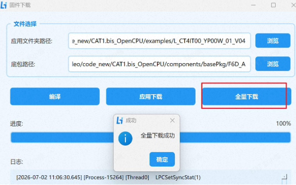
A USB data cable is required for power supply, communication, and flashing. Connect the PC and NT26FxDx OpenKit with a USB data cable, then press and hold the power button for more than 3 seconds.
Driver Installation
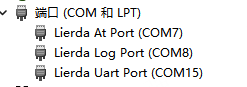
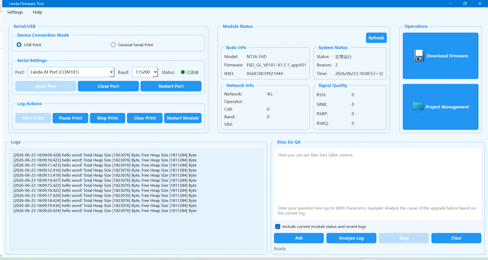
For driver installation, refer to Lierda EigenComm Cat.1 bis Module USB Driver Installation Guide. After installation, the Lierda USB port can be seen in Device Manager.
Indicator Lights
NT26FxDx OpenKit indicates charging and operating status through the charging indicator and RGB indicator.
Charging Indicator
When USB is not connected, the charging indicator is off
When USB is connected, the charging indicator is red, indicating normal charging
When USB is connected, the charging indicator is green, indicating the battery is fully charged
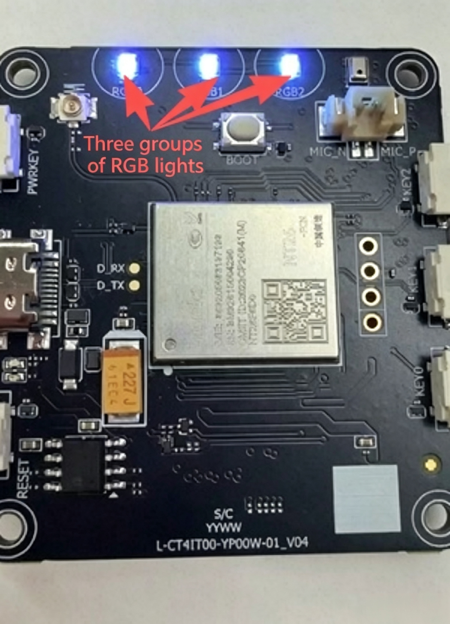
RGB Indicator
When powered off, the RGB indicator is off
When powered on, the RGB indicator stays solid green during normal operation
When powered on, the RGB indicator flashes blue during voice interaction
When powered on, the RGB indicator stays solid red in an abnormal state, such as network failure
When powered on, the RGB indicator flashes green three times before shutdown
Hardware Reference
Functional Block Diagram
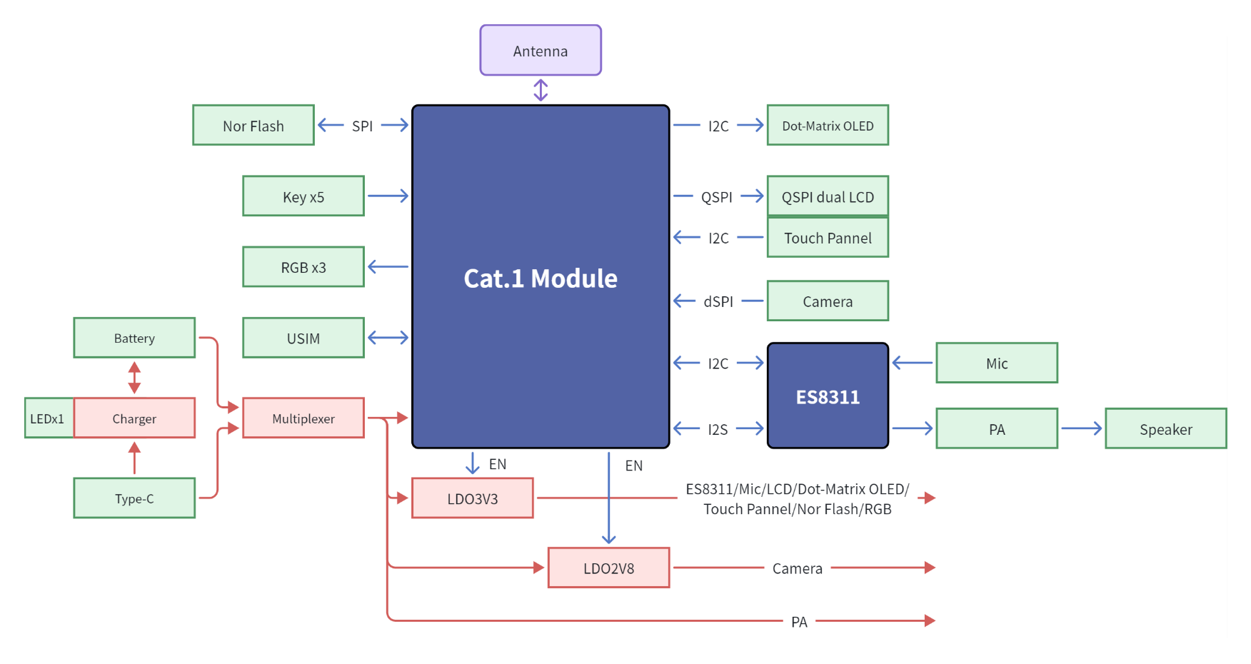
The functional block diagram of NT26FxDx OpenKit is shown below.
Power Supply Methods
The main board includes a power switching circuit, and the system can be powered in the following ways:
Powered by Battery The device integrates a 3.7V lithium battery internally. Press the power button for 3 seconds to power it on.
Powered by Type-C Port Insert a Type-C USB data cable into the USB interface. The system power automatically switches to Type-C power supply. If the
Charge_DETfunction is enabled, the device can power on when USB is inserted. If theCharge_DETfunction is not enabled, press the power button for 3 seconds to power it on.
Charging Circuit
USB Interface
SIM Card Interface
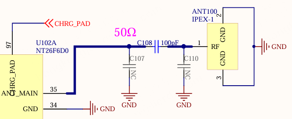
RF Interface
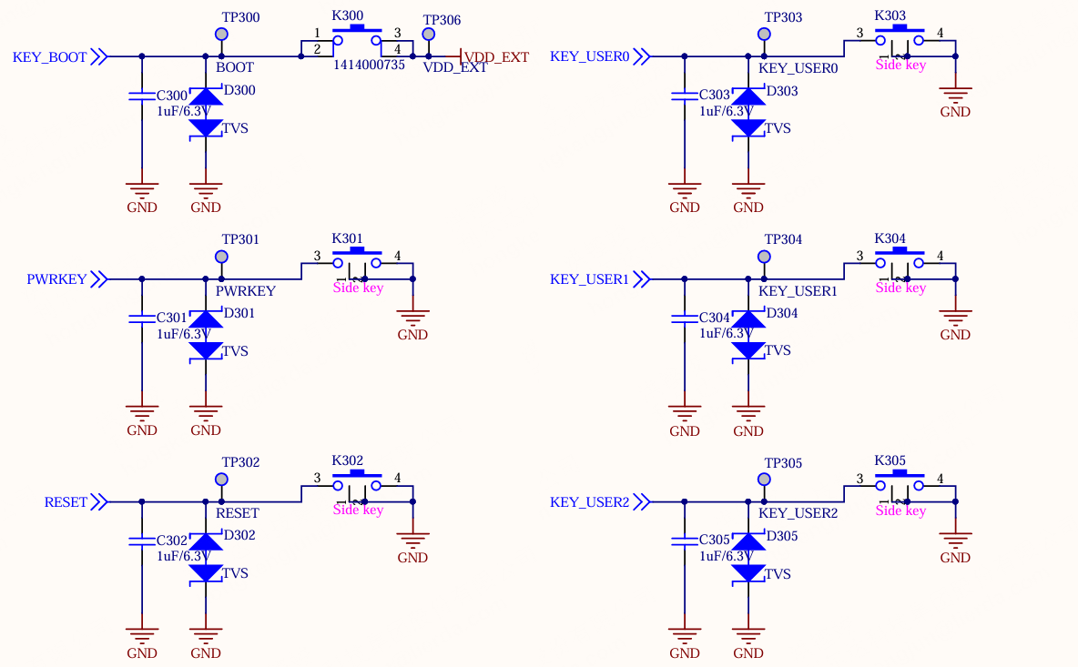
Button Interface
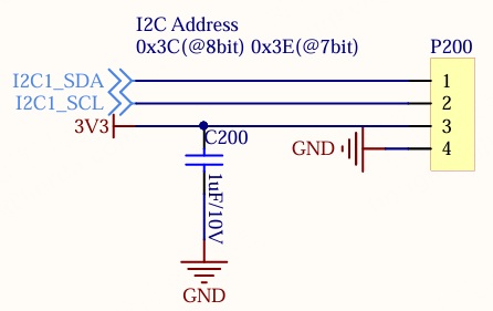
Dot-Matrix Display Interface
LCD Interface
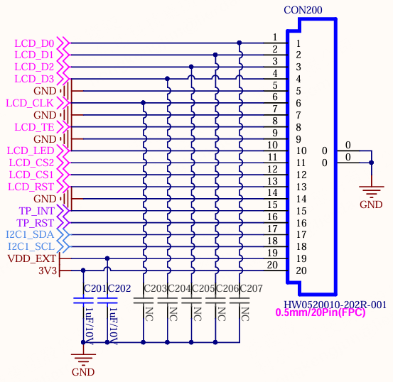
When using an SPI display, the following pins are available:
Display Pin Reference |
Corresponding Net Name |
|---|---|
VCC |
3V3 |
IOVCC |
VDD_EXT |
TE |
LCD_TE |
SDA |
LCD_D0 |
DC |
LCD_D1 |
SCL |
LCD_CLK |
CS |
LCD_CS1/LCD_CS2*(1)* |
RST |
LCD_RST |
GND |
GND |
A |
3V3 |
K |
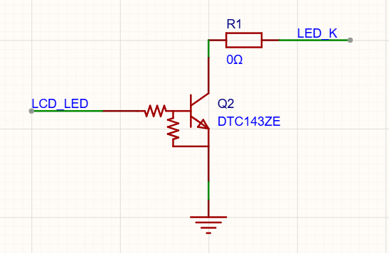
LCD_LED ctrl NPN*(2)* |
To debug the dual-screen function, one
0Rresistor needs to be soldered atR120to connect theLCD_CS2pin.I2C1_SCLandLCD_CS2cannot be used at the same time, which means the dot-matrix display and touch panel cannot be used together with the dual-screen configuration.
LCD_LEDcontrols the backlight cathode as theENpin. It is recommended to reserve a current-limiting resistor. The reference circuit of the adapter board is shown below:
When using a QSPI display, the following pins are available:
Display Pin Reference |
Corresponding Net Name |
|---|---|
GND |
3V3 |
LCD_RS |
NC*(1)* |
LCD_CS |
LCD_CS1/LCD_CS2*(2)* |
LCD_CLK |
LCD_CLK |
LCD_D3 |
LCD_D3 |
LCD_D2 |
LCD_D2 |
LCD_D1 |
LCD_D1 |
LCD_D0 |
LCD_D0 |
LCD_RT |
LCD_RST |
VDD3.3 |
3V3 |
VDD3.3 |
3V3 |
LEDA |
3V3 |
LEDK |
LCD_LED ctrl NPN*(3)* |
LCD_TE |
LCD_TE |
GND |
3V3 |
RS(Register Select) may also be namedDC(Data/Command). Some controllers do not define this pin, such as theGC9B72NAcontroller. In that case, the unusedLCD_CSpin can be multiplexed as a GPIO for control.Same as for the SPI display and not repeated here.
Same as for the SPI display and not repeated here.
When using the touch panel (TP), the following pins are available:
Touch Panel Pin Reference |
Corresponding Net Name |
|---|---|
VDD |
3V3 |
SDA |
I2C1_SDA |
SCL |
I2C1_SCL |
INT |
TP_INT |
RST |
TP_RST |
GND |
GND |
Camera Interface
Audio Interface
Codec Chip
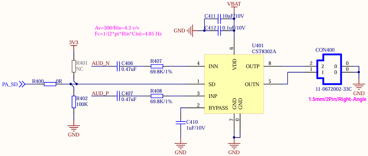
Microphone Interface
Speaker Interface
Indicator Light Interface
RGB Indicator Light
Charging Indicator Light
Software Reference
OpenKit demo_watch Feature and Module Description
Document Purpose
demo_watch is a watch application example implemented based on LIOT, LVGL, and the application framework.
This document only explains two parts:
Functional pages that users can see and operate.
Responsibility boundaries and resource management principles of each module.
This document does not cover specific function implementations, internal task flows, or debug logs. When adding new features in the future, priority should be given to supplementing the corresponding UI entry, functional modules, resources, and return relationships.
UI Overview
Page Structure
The current page relationships are as follows:
Home
├── Camera Preview
├── Scan Preview
├── GIF
├── Player List
│   └── Player Now Playing
└── Recorder
Page return rules:
Camera Preview,Scan Preview,GIF,Recorderreturn toHome.Player Now Playingreturns toPlayer List.Player Listreturns toHome.Homeis the root page and does not continue to return.When exiting Camera, Scan, GIF, Player, Recorder and other functions, the business should be stopped first, then return to the page.
User-Visible Features
Main Interface
The main interface uses a white background, reserves a status bar at the top, and displays 3 x 3 grid function buttons below.
The current grid entries include:
Camera
Scan
Player
Recorder
GIF
Settings
Tools
OTA
About
Among them, Settings, Tools, OTA, and About are currently reserved entries, and specific functions will be connected later.
Status Bar
The status bar is located at the top of the screen and is currently used to display:
Fixed title
Watch AI.Current status text, such as
IDLE,CAMERA,GIF, etc.Current mood or running status indicator, such as
ON,AI,REC,ERR.
Information such as time, network, and battery can be added after connecting to the status bar data source in the future, and is not currently described as an implemented feature.
Camera Preview
The Camera page is used to display real-time camera images.
Users can see:
Status bar at the top.
Camera preview area below the status bar.
Camera messages or prompt text.
Main behaviors:
Start the camera session after entering the page.
Continuously capture camera frames and display the latest image.
Swipe left or right to exit the preview.
When exiting, stop the camera session and release camera frame buffers and display buffers.
Scan QR Code
The Scan page is used for QR code or barcode recognition.
Users can see:
Status bar at the top.
Camera preview image.
Scan prompt or scan result.
Main behaviors:
Camera outputs grayscale images according to scan configuration.
Call the scan decoding library after obtaining the image.
Continue to capture and recognize when no code is detected.
Save the result after successful recognition and notify the application layer to update the display.
Swipe left or right to exit scanning.
Scan shares the camera session and page display capabilities with Camera, but scan decoding is handled by an independent Scan module.
GIF Playback
The GIF page is used to play demonstration animations.
Users can see:
Status bar at the top.
GIF animation area below the status bar.
Main behaviors:
Create a GIF playback object and start playback when entering the page.
The playback process is completed by the LVGL display layer and the GIF/VPU adaptation layer.
Stop playback and release the playback object when exiting the page.
The current GIF demo resources participate in compilation as project resources. In the future, it can be expanded to read files from external Flash.
Player File List
The Player page is used to browse and select audio files.
The current list supports:
MP3 files.
WAV files.
TTS entry.
External Flash file list.
Vertical scrolling when there are many files.
The TTS item is displayed at the top of the list. MP3 and WAV items display the file name, format, and file size.
User operations:
Click on a file to enter the playback page.
Swipe left or right to return to the main interface.

Player Playback Page
The playback page is used to display the current playback status.
Users can see:
Current file name.
File format and file size.
Playback progress bar.
Playback percentage or progress text.
Playing,DoneorStoppedstatus.
When playing TTS, it displays TTS Play and does not display the internal TTS path or text encoding.
Page relationship:
Enter
Player Now Playingby clicking on a file fromPlayer List.Swipe left or right to return to
Player List.Release current playback resources when playback stops, completes, or exits.
Recorder Standby Page
After entering Recorder, recording does not start immediately. The page is first in the standby state.
Users can see:
Recording title.
Current recording file name or file name to be generated.
Audio sampling parameters.
Recording duration.
File size.
Level bar.
Startbutton.
Recorder Recording Page
Recording starts after clicking Start.
Users can see:
Recording file name.
Recording duration continuously increasing.
File size continuously increasing.
Level bar changing with input sound.
Stopbutton.
After clicking Stop, stop capturing and save the WAV file. During the saving period, the page displays the saving status to avoid repeated user operations.
Recorder Save Completed
After saving is completed, the page displays the final recording information and Saved status.
When storage space is insufficient or saving fails, the page displays a corresponding prompt and does not continue to write data to the file.
Function Module Responsibilities
Camera
The Camera module is responsible for camera preview business:
Initialize and close the camera.
Manage camera sessions.
Obtain camera images.
Pass images to the display module.
Stop capturing and release buffers when exiting preview.
Camera is not responsible for scan decoding or page control creation.
Scan
The Scan module is responsible for QR code or barcode recognition:
Use grayscale camera configuration required for scanning.
Receive camera capture data.
Call the scan decoding library.
Save recognition results.
Notify the application layer to display results.
Scan can reuse Camera’s capture session, but the decoding logic remains independent for easy addition of other recognition algorithms in the future.
GIF
The GIF module is responsible for animation playback business:
Start and stop GIF playback.
Manage GIF playback objects.
Use GIF/VPU adaptation capabilities provided by the display layer.
Release decoding and playback resources when exiting the page.
The GIF business does not directly handle LCD or LVGL underlying refresh details.
Player
The Player module is responsible for audio playback business and file list:
Enumerate MP3/WAV files in external Flash.
Manage TTS playback entry.
Handle file selection, playback, stop, and completion status.
Update playback progress and page status.
Release file list, playback tasks, and playback buffers when exiting.
Player can be expanded to support AMR, AAC and other formats in the future. When adding new formats, priority should be given to adding file types and corresponding platform playback adaptation, without changing page return and session management rules.
Player is not responsible for public call links or recording.
Recorder
The Recorder module is responsible for recording, saving, and recording status:
Create recording file names.
Start and stop recording.
Receive audio capture data.
Generate WAV file header and write to external Flash.
Update duration, file size, and level bar.
Handle insufficient storage space.
Release recording resources when saving is completed or exiting.
Recorder can add recording file list and playback in the future, but recording capture and Player playback still maintain separation of responsibilities.
Audio
watch_audio only retains common audio capabilities:
Audio hardware initialization.
Playback and recording underlying interfaces.
Audio codec lifecycle management.
Sample rate switching.
Underlying deinit after playback or recording stops.
Specific businesses are managed by upper-layer modules:
MP3, WAV, TTS: Managed by Player.
Recording: Managed by Recorder.
Public voice input, calls, etc.: Managed by Audio or subsequent independent Call modules.
Software Layering
Application Layer
Directory:
apps/watch_ai_app/
The application layer is responsible for:
Application startup and initialization.
User operation dispatch.
Page switching.
Function session management.
Coordinating Camera, Scan, Player, Recorder, GIF and other modules.
Main modules:
watch_display
watch_camera
watch_scan
watch_player
watch_recorder
watch_gif
watch_audio
watch_page
watch_session
watch_action
Service Layer
Directory:
framework/services/
The service layer defines common capabilities and data interfaces, such as:
Display Service
Camera Service
Scan Service
Player Service
Recorder Service
Storage Service
The service layer is not directly bound to specific LCD, camera, audio codec, or external Flash chips.
Platform Adaptation Layer
Directory:
framework/platform/
The platform layer connects common services to LIOT and specific hardware:
camera/: Camera adaptation.display/: LCD, LVGL, TP, and GIF display adaptation.player/: MP3, WAV, TTS playback adaptation.recorder/: Recording adaptation.scan/: Scan decoding adaptation.board/: Board-level hardware initialization.osal/: Operating system adaptation for tasks, memory, delays, etc.
Core Framework
Directory:
framework/core/
The core framework is responsible for:
Application events.
Application state.
Basic error definitions.
Core initialization and event handling.
Page stack and function sessions are maintained by application layer modules. The core layer is not bound to specific business pages.
Lifecycle and Resource Principles
Function resources are managed in a “request on entry, release on exit” manner.
Main resources include:
Camera frame buffers.
LVGL preview buffers.
Scan decoding buffers.
GIF decoding and playback resources.
Audio playback buffers.
Recording buffers.
External Flash file handles.
Function-specific tasks.
Function-specific synchronization objects.
The basic order when exiting a page:
Stop business
    ↓
Wait for task or data processing to end
    ↓
Close files, devices, or decoders
    ↓
Release buffers and synchronization objects
    ↓
Close session
    ↓
Return to previous page
Board-level initialization and system-level services can be resident; function-specific resources such as Camera, Scan, GIF, Player, and Recorder should not be occupied unconditionally for a long time.
Page, Session, and Return Relationships
Pages are responsible for display and user operations, functional modules are responsible for business, and sessions ensure that only one exclusive function runs at a time.
Example relationships:
Home
  └─ Camera Preview
       └─ Camera Session

Home
  └─ Scan Preview
       └─ Camera Session + Scan

Home
  └─ Player List
       └─ Player Now Playing
            └─ Player Session

Home
  └─ Recorder
       └─ Recorder Session

Home
  └─ GIF
       └─ GIF Session
Left and right swipes uniformly produce return actions. The application layer processes them in the following order:
First stop the current function session.
Then release current function resources.
Return to the previous page according to the page hierarchy.
Update the status bar and application state.
Future Extension Rules
When adding photo capture, more audio formats, recording playback, calls, network pages, OTA pages, or settings pages in the future, extend according to the following boundaries:
Add a UI entry on the home page.
Add a corresponding business module at the application layer.
Add independent service interfaces when necessary.
Add hardware adaptation at the platform layer.
Define independent pages and sessions for functions.
Clarify resources requested on entry and released on exit.
Add page screenshots and return relationship descriptions.
New functions should not write underlying hardware operations directly into LVGL pages, nor should multiple business functions continue to be piled into app_main.c or an existing module.