PWM 开发指导_Rev1.0
1 修订记录
版本 |
日期 |
作者 |
修订内容 |
|---|---|---|---|
Rev1.0 |
2023-09-12 |
WTY |
创建文档 |
Rev1.1 |
2024-03-25 |
SXX |
更改文档名称 |
Rev1.2 |
2025-02-12 |
ZLC |
新增liot_pwm_set_duty_cycle接口 |
Rev1.3 |
2026-03-18 |
ZLC |
新增APWM接口 |
Rev1.4 |
2026-04-21 |
ZXQ |
根据审核修改 |
2 简介
2.1 文档简介
本文档介绍 LTE-EC71X PWM 接口 API 情况, API 接口位于 LSDK/components/kernel/lierda_api/liot_pwm/liot_pwm.h 文件声明。
LTE-EC71X 系列模组支持 6 路 PWM 输出,每路都支持选择 26MHz 高速时钟和 40KHz 低速时钟源,1~256 时钟分频。
2.2 pwm原理简介
脉宽调制(Pulse Width Modulation)是一种通过调整脉冲信号的占空比来控制平均输出电压的技术。占空比是指高电平时间占整个周期的比例。通过改变占空比,可以控制连接到PWM输出的负载(如电机、LED等)的平均功率。
在LTE-EC71X模组中,PWM控制器通过可编程的时钟分频器、周期寄存器和占空比寄存器生成精确的PWM波形:
时钟源选择:可选择26MHz高速时钟或40KHz低速时钟
分频系数:寄存器值是0~255分频(实际是1~256),用于调整基础时钟频率
周期寄存器:决定PWM波形的总周期时间,也就是pwm波的频率
占空比寄存器:决定低电平在周期内的持续时间
输出频率计算公式:f = 时钟源频率 / (分频系数 + 1) / (周期值 + 1) 占空比计算公式:占空比 = (周期值 + 1 - 占空比值) / (周期值 + 1)
2.3 pwm驱动能力
在本模组中,驱动能力的设置,不同的芯片平台会有不同的默认设置,暂时无法动态设置。
3 API 函数概览
函数 |
说明 |
|---|---|
liot_pwm_open() |
打开 PWM 功能 |
liot_pwm_close() |
关闭 PWM 功能 |
liot_pwm_enable() |
使能 PWM 并配置 PWM 的脉冲周期和占空比 |
liot_pwm_disable() |
暂停 PWM 功能 |
liot_pwm_set_duty_cycle() |
设置PWM占空比 |
4 类型说明
4.1 liot_pwm_errcode_e
PWM 错误码表示函数是否执行成功,若失败则返回错误原因,枚举信息定义如下:
声明
typedef enum{
    LIOT_PWM_SUCCESS = LIOT_SUCCESS,
    LIOT_PWM_EXECUTE_ERR = 1 | LIOT_PWM_ERRCODE_BASE,
    LIOT_PWM_INVALID_PARAM_ERR,
    LIOT_PWM_FUNC_SET_ERR,
    LIOT_PWM_ACQUIRE_ERR,
    LIOT_PWM_START_ERR,
    LIOT_PWM_STOP_ERR,
    LIOT_PWM_REPEAT_OPEN_ERR,
    LIOT_PWM_REPEAT_CLOSE_ERR,
} liot_pwm_errcode_e;
参数
LIOT_PWM_SUCCESS :函数执行成功
LIOT_PWM_EXECUTE_ERR :函数执行失败
LIOT_PWM_INVALID_PARAM_ERR:参数错误
LIOT_PWM_FUNC_SET_ERR:PWM 功能设置失败
LIOT_PWM_ACQUIRE_ERR:PWM 信息获取失败
LIOT_PWM_START_ERR:PWM 功能启用失败
LIOT_PWM_STOP_ERR:PWM 功能停止失败
LIOT_PWM_REPEAT_OPEN_ERR:PWM 重复打开错误
LIOT_PWM_REPEAT_CLOSE_ERR:PWM 重复关闭错误
4.2 liot_pwm_sel_e
PWM 通道类型枚举信息定义如下:
声明
typedef enum{
    LIOT_PWM_0,
    LIOT_PWM_1,
    LIOT_PWM_2,
    LIOT_PWM_3,
    LIOT_PWM_4,
    LIOT_PWM_5,
    LIOT_PWM_MAX,
} liot_pwm_sel_e;
参数
LIOT_PWM_0 :PWM 通道 0
LIOT_PWM_1 :PWM 通道 1
LIOT_PWM_2 :PWM 通道 2
LIOT_PWM_3 :PWM 通道 3
LIOT_PWM_4 :PWM 通道 4
LIOT_PWM_5 :PWM 通道 5
说明
PWM 通道对应引脚号参考Lierda NT26F OpenCPU 模组IO复用表
4.3 liot_pwm_clk_e
PWM 时钟源,枚举信息定义如下:
声明
typedef enum{
    LIOT_CLK_RC26M,
    LIOT_CLK_RTC_40K,
} liot_pwm_clk_e;
参数
LIOT_CLK_RC26M:RC 振荡器时钟源,频率:26 Mhz
LIOT_CLK_RTC_40K:RTC 时钟源,频率:40 Khz
4.4 liot_pwm_cfg_s
PWM 参数配置结构体信息定义如下:
声明
typedef struct{
    liot_pwm_clk_e clk_sel;
    uint16_t prescaler;
    uint16_t period;
    uint16_t duty;
} liot_pwm_cfg_s;
参数
clk_sel:PWM 时钟源,详见 4.3 liot_pwm_clk_e
prescaler:分频系数,范围 0~255
period:自动加载计数器的值
duty:高电平对应的计数值
说明
输出频率 f = 时钟源频率 / (prescaler + 1) / (period + 1)。
占空比 = (period + 1 - duty) / (period + 1)。
5 API 函数详解
5.1 liot_pwm_open
该函数用于打开 PWM 功能。
声明
liot_pwm_errcode_e liot_pwm_open(liot_pwm_sel_e pwm_sel);
参数
pwm_sel:[In] PWM 通道。详情请参考4.2 liot_pwm_sel_e。
返回值
liot_pwm_errcode_e:执行结果码,请参考 4.1 节说明。
5.2 liot_pwm_close
该函数用于关闭 PWM 功能。
声明
liot_pwm_errcode_e liot_pwm_close(liot_pwm_sel_e pwm_sel);
参数
pwm_sel:[In] PWM 通道。详情请参考4.2 liot_pwm_sel_e。
返回值
liot_pwm_errcode_e:执行结果码,请参考 4.1 节说明。
5.3 liot_pwm_enable
该函数用于使能 PWM 功能,同时会配置liot_pwm_cfg_s中的时钟源、预分频系数、脉冲周期和占空比。
声明
liot_pwm_errcode_e liot_pwm_enable(liot_pwm_sel_e pwm_sel, liot_pwm_cfg_s *pwm_cfg);
参数
pwm_sel:[In] PWM 通道。详情请参考4.2 liot_pwm_sel_e。
pwm_cfg:[In] 使能 PWM 时需要配置的参数。详情请参考4.4 liot_pwm_cfg_s。
返回值
liot_pwm_errcode_e:执行结果码,请参考 4.1 节说明。
5.4 liot_pwm_disable
该函数用于暂停 PWM 功能。
声明
liot_pwm_errcode_e liot_pwm_disable(liot_pwm_sel_e pwm_sel);
参数
pwm_sel:[In] PWM 通道。详情请参考4.2 liot_pwm_sel_e。
返回值
liot_pwm_errcode_e:执行结果码,请参考 4.1 节说明。
5.5 liot_pwm_set_duty_cycle
该函数用于设置PWM占空比,不会改变pwm波的频率。
声明
liot_pwm_errcode_e liot_pwm_set_duty_cycle(liot_pwm_sel_e pwm_sel, uint32_t duty_cycle);
参数
pwm_sel:[In] PWM 通道。详情请参考4.2 liot_pwm_sel_e。
duty_cycle:[In] 计数器比较值。
返回值
liot_pwm_errcode_e:执行结果码,请参考 4.1 节说明。
6 代码示例
示例代码参考 LSDK/examples/demo/src/demo_pwm.c 文件。
C/**
 * @file liot_pwm_demo.c
 * @brief LIoT PWM (Pulse Width Modulation) Demo Application
 * @date 2025-08-26
 * @version 1.0
 * @copyright Copyright (c) 2025 Lierda Technology Co., Ltd.
 */
 /**
 * This demo application demonstrates the usage of PWM (Pulse Width Modulation) peripherals
 * on EC7xx series chips. It initializes multiple PWM channels with different configurations
 * and demonstrates dynamic duty cycle adjustment on one channel.
 */

#include <stdio.h>
#include <string.h>

#include "lierda_app_main.h"
#include "liot_gpio2.h"
#include "liot_os.h"
#include "liot_pwm.h"

#define DEMO_PWM_1_PIN      (20)   /**< PWM1 channel GPIO pin for EC718 */
#define DEMO_PWM_1_FUCN     (5)    /**< PWM1 channel function selector for EC718 */
#define DEMO_PWM_2_PIN      (106)  /**< PWM2 channel GPIO pin for EC718 */
#define DEMO_PWM_2_FUCN     (5)    /**< PWM2 channel function selector for EC718 */
#define DEMO_PWM_3_PIN      (25)   /**< PWM3 channel GPIO pin for EC718 */
#define DEMO_PWM_3_FUCN     (5)    /**< PWM3 channel function selector for EC718 */

/** @} */ // end of PWM_DEMO_HARDWARE_CONFIG

/** @defgroup PWM_DEMO_PARAMETERS PWM Demo Parameters
 *  @brief Configuration parameters for PWM demonstration
 *  @{
 */
#define PWM_UPDATE_INTERVAL_MS 500   /**< Duty cycle update interval in milliseconds */
#define PWM_MAX_DUTY_CYCLE     2000  /**< Maximum duty cycle value for PWM2 */
#define PWM_DUTY_STEP          200   /**< Duty cycle increment step */
/** @} */ // end of PWM_DEMO_PARAMETERS

/**
 * @brief PWM demonstration thread
 *
 * This thread initializes three PWM channels with different configurations:
 * - PWM1: 10kHz frequency
 * - PWM2: 500Hz frequency with dynamic duty cycle adjustment
 * - PWM3: 100Hz frequency
 *
 * The thread continuously adjusts the duty cycle of PWM2 from 0 to max value
 * and back to 0 in steps, demonstrating dynamic PWM control.
 *
 * @param[in] argv Thread argument (not used in this demo)
 */
void liot_pwm_demo_thread(void *argv)
{
    liot_pwm_cfg_s ptr;               /**< PWM configuration structure */
    uint16_t duty_cycle = 0;          /**< Current duty cycle value for PWM2 */

    // Power management: Enable AON (Always-On) domain power
    Liot_AonPowerCtl(true);

    // Configure GPIO pins for PWM functionality
    // Must set pin func to pwm before use
    Liot_SetPinFunc(DEMO_PWM_1_PIN, DEMO_PWM_1_FUCN);
    Liot_SetPinFunc(DEMO_PWM_2_PIN, DEMO_PWM_2_FUCN);
    Liot_SetPinFunc(DEMO_PWM_3_PIN, DEMO_PWM_3_FUCN);

    /** @brief PWM1 configuration: 10kHz frequency
     *  Calculation: PWM frequency = (Clock frequency) / ((period + 1) * (prescaler + 1))
     *  With RC26M clock (26MHz), period=99, prescaler=25:
     *  Frequency = 26,000,000 / ((99 + 1) * (25 + 1)) = 26,000,000 / 2600 = 10,000Hz = 10kHz
     */
    ptr.clk_sel   = LIOT_CLK_RC26M;   /**< Select 26MHz RC oscillator as clock source */
    ptr.duty      = 10;               /**< Initial duty cycle (10/100 = 10%) */
    ptr.period    = 99;               /**< PWM period value */
    ptr.prescaler = 25;               /**< Clock prescaler value */
    liot_pwm_enable(LIOT_PWM_1, &ptr);/**< Apply configuration to PWM1 */
    liot_pwm_open(LIOT_PWM_1);        /**< Enable PWM1 output */

    /** @brief PWM2 configuration: 500Hz frequency
     *  With RC26M clock (26MHz), period=1999, prescaler=25:
     *  Frequency = 26,000,000 / ((1999 + 1) * (25 + 1)) = 26,000,000 / 52,000 = 500Hz
     */
    ptr.duty      = 500;              /**< Initial duty cycle (500/2000 = 25%) */
    ptr.period    = 1999;             /**< PWM period value */
    ptr.prescaler = 25;               /**< Clock prescaler value */
    liot_pwm_enable(LIOT_PWM_2, &ptr);/**< Apply configuration to PWM2 */
    liot_pwm_open(LIOT_PWM_2);        /**< Enable PWM2 output */

    /** @brief PWM3 configuration: 100Hz frequency
     *  With RC26M clock (26MHz), period=9999, prescaler=25:
     *  Frequency = 26,000,000 / ((9999 + 1) * (25 + 1)) = 26,000,000 / 260,000 = 100Hz
     */
    ptr.duty      = 2000;             /**< Initial duty cycle (2000/10000 = 20%) */
    ptr.period    = 9999;             /**< PWM period value */
    ptr.prescaler = 25;               /**< Clock prescaler value */
    liot_pwm_enable(LIOT_PWM_3, &ptr);/**< Apply configuration to PWM3 */
    liot_pwm_open(LIOT_PWM_3);        /**< Enable PWM3 output */

    // Initial delay to ensure stable PWM output
    liot_rtos_task_sleep_ms(1000);

    // Main loop: Dynamic duty cycle adjustment for PWM2
    while (1)
    {
        liot_trace("LIOT_PWM_2 duty cycle:%d/%d\r\n", duty_cycle, PWM_MAX_DUTY_CYCLE);
        liot_pwm_set_duty_cycle(LIOT_PWM_2, duty_cycle); /**< Update PWM2 duty cycle */
        liot_rtos_task_sleep_ms(PWM_UPDATE_INTERVAL_MS); /**< Wait for next update */
        duty_cycle += PWM_DUTY_STEP;                     /**< Increment duty cycle */

        // Reset duty cycle when exceeding maximum value
        if(duty_cycle > PWM_MAX_DUTY_CYCLE)
        {
            duty_cycle = 0;  /**< Reset to minimum duty cycle */
        }
    }
    liot_pwm_close(LIOT_PWM_1);
    liot_pwm_close(LIOT_PWM_2);
    liot_pwm_close(LIOT_PWM_3);

    liot_pwm_disable(LIOT_PWM_1);
    liot_pwm_disable(LIOT_PWM_2);
    liot_pwm_disable(LIOT_PWM_3);

    liot_rtos_task_delete(NULL); // kill itsel
}
运行结果:
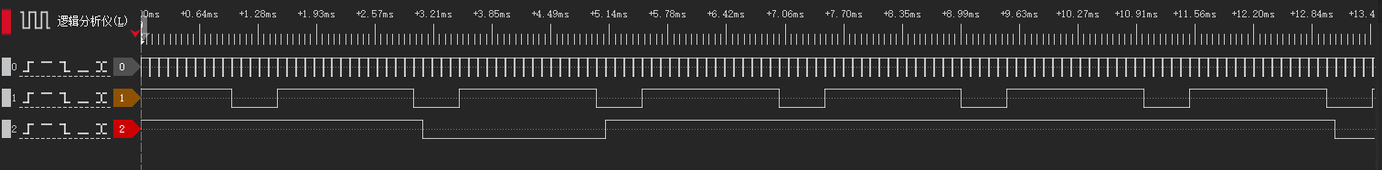
运行 DEMO 程序后模组共输出三路 PWM 信号,上图为逻辑分析仪捕获的信号,频率分别为10KHz、500Hz、100Hz,其中pwm2 500HZ的pwm波的占空比会不断变化。