XiaoDa AI-Core Box_Rev0.2
[!NOTE] Note Please remove the enclosure and check the silkscreen model and version on the main board to confirm that your development board version corresponds to the application guide document.
Xiaoda is an embedded core module integrating voice recognition, audio playback, and intelligent interaction, specifically designed for smart toys, educational devices, and interactive terminals. This movement incorporates a main control chip, audio system, and power supply module, enabling voice wake-up, conversational interaction, content playback, and other functions.
This application guide will help you get started quickly with Xiaoda and provide detailed information about this development board.
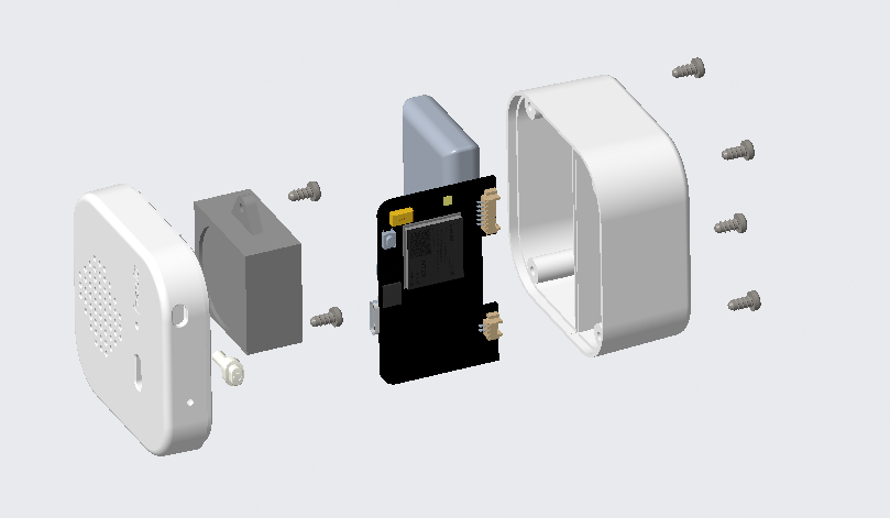
This guide includes the following content:
Hardware Version: Introduces hardware version history and known issues.
Getting Started: Provides a brief introduction to the development board and hardware/software setup guide.
Hardware Reference: Provides detailed information about the development board hardware.
Software Reference: Provides detailed information about the software framework, modules, and configuration methods.
Related Resources: Lists links to related documents.
Hardware Version
This document only applies to the Xiaoda main board model: L-CT4IT00-YP00W-03A_V04.
PCB Model |
PCB Version |
Change Log |
|---|---|---|
L-CT4IT00-YP00W-03A |
V04 |
/ |
Getting Started
This section provides a brief introduction to Xiaoda, explaining how to flash firmware and related preparation work.
Component Introduction
Main Components (TOP) |
Description |
|---|---|
L-CT4IT00-YP00W-03A_V04 |
Main Board PCB |
shell |
Enclosure |
103040A1 |
Battery |
JMO-627BA283H-1AXD63 |
Microphone |
2831NROOO-4P25D13H |
Speaker |
13P023M |
Antenna |
 L-CT4IT00-YP00W-03A_V04 (Main Board PCB)
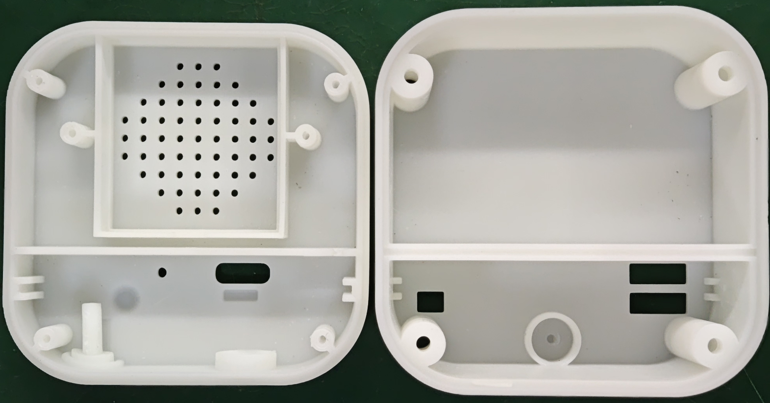 shell(Enclosure)
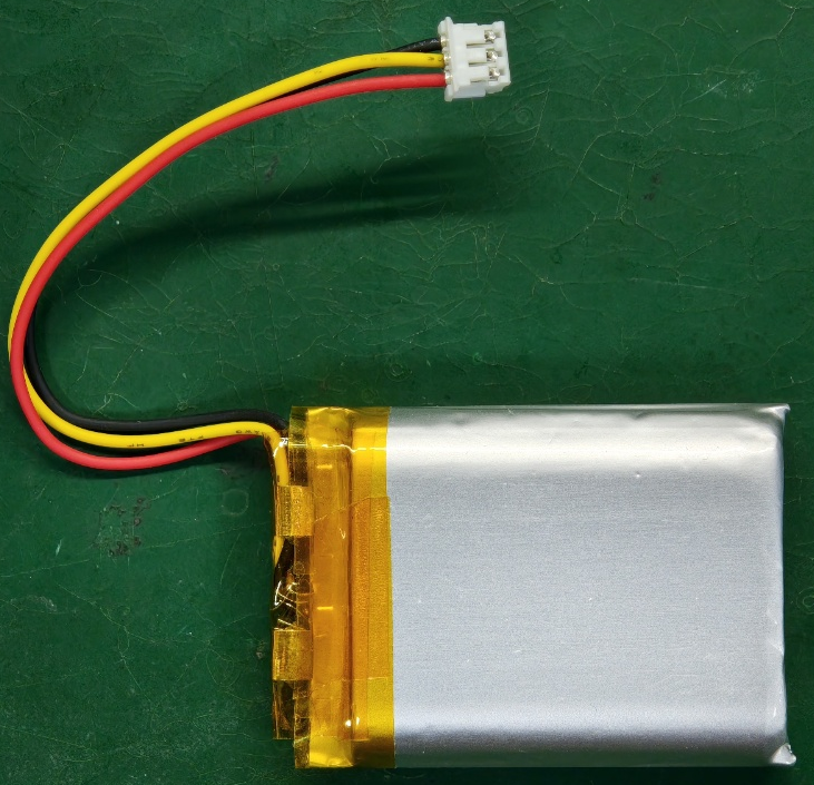 103040A1 (Battery)
 JMO-627BA283H-1AXD63 (Microphone)
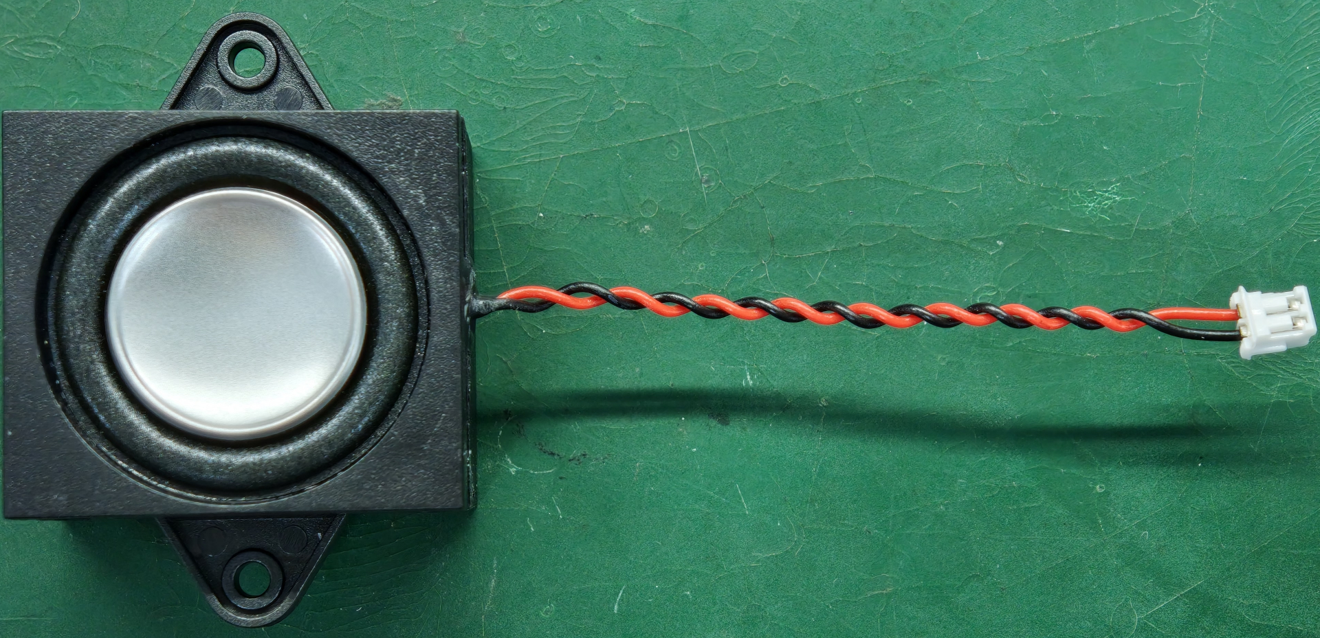 2831NROOO-4P25D13H (Speaker)
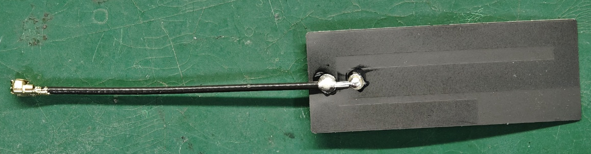 13P023M (Antenna)
Main Board Introduction
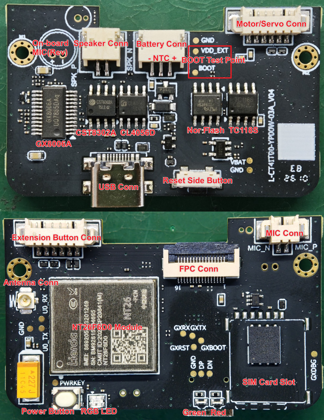
The main components and interfaces of L-CT4IT00-YP00W-03A_V04 are described below:
Main Components (TOP) |
Description |
|---|---|
Onboard MIC (Reserved) |
Either this or the microphone connector can be used |
Speaker Connector |
1.5mm/2PIN connector socket for connecting 4Ω/3W speaker |
Battery Connector*(1)* |
1.5mm/3PIN connector socket, compatible with battery 103040A1 |
BOOT Test Point |
Used to force entry into download mode when the module is bricked |
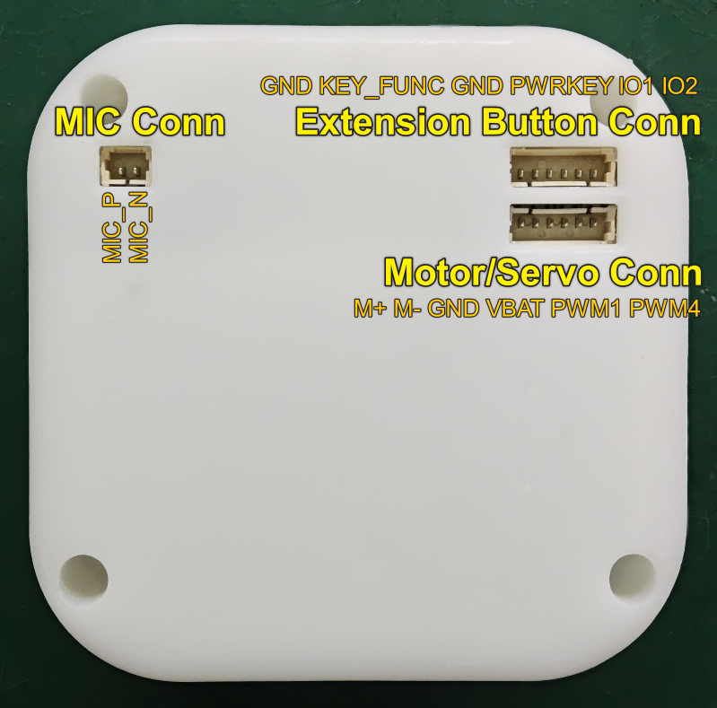
Motor/Servo Connector*(2)* |
1.25mm/6PIN connector socket, provides 2-channel PWM/power/H-bridge differential output, use as needed |
GX8006A |
Offline voice chip with local AEC (Acoustic Echo Cancellation) and custom wake word capability |
CST8302A |
AB/D class amplifier, AB class recommended for better AEC performance |
CL4056D |
Charge management chip, suitable for 4.2V battery, NTC recommended R25=100KΩ |
Nor flash |
Nor flash chip, 32Mbit, suitable for 3.3V systems |
TC118S |
H-bridge driver chip |
USB Connector |
Type-C interface connector for power supply, charging, communication, and download |
Reset Side Button |
Reset, used to reset the module |
Main Components (BOT) |
Description |
Antenna Socket |
IPEX-1 generation socket, compatible |
Extension Button Connector*(3)* |
1.25mm/6PIN connector socket, provides PWRKEY and 3 custom buttons (2 pins can be multiplexed as UART) |
NT26F6D0 Module |
Cat.1 module, supports OPEN application development |
FPC Connector*(4)* |
0.5mm/16PIN FPC connector for connecting binocular screen adapter board |
Microphone Connector |
1.25mm/2PIN connector socket for connecting electret microphone |
Power Button |
Pwrkey, used for system power on/off |
RGB LED |
RGB indicator light, indicates module working status |
Green LED |
Charge complete indicator, stays on when fully charged |
Red LED |
Charging status indicator, stays on during charging |
SIM Card Slot |
Nano-SIM card slot connector for SIM card reading |
[!NOTE] Note
When using the battery connector, ensure the battery terminal wire sequence corresponds to the connector wire sequence
When using the motor/servo connector, pay attention to the wire sequence; motors and servos are not included in the Xiaoda product package
When using the extension button connector, pay attention to the wire sequence; the button extension board is not included in the Xiaoda product package
When using the FPC connector, pay attention to the wire sequence; the binocular screen adapter board is not included in the Xiaoda product package
Enclosure Interfaces
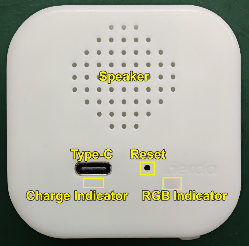
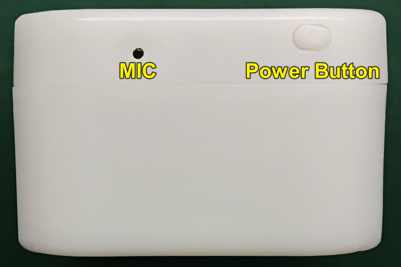
Key enclosure interfaces are described below:
Interface (TOP) |
Description |
|---|---|
Speaker |
Speaker sound mesh |
Type-C |
Type-C interface, connects PC and Xiaoda for power supply, charging, communication, and download |
Charging Indicator |
Indicates charging status: red light during charging, green light when fully charged |
RGB Indicator |
Indicates working status |
Reset |
Reset hole, use a SIM eject pin to reset the system |
Interface (Side) |
Description |
MIC |
Microphone pickup hole |
Power Button |
Long press to power on when off, long press to power off when on |
Interface (BOT) |
Description |
MIC Interface |
Used when connecting an external microphone, pay attention to wire sequence |
Extension Button Interface |
External button extension, IO1/IO2 can be multiplexed as UART, pay attention to wire sequence |
Motor/Servo Interface |
External motor/servo, built-in H-bridge driver circuit, M+/M- can connect DC motor, pay attention to wire sequence |
Start Using
Visually inspect the product appearance for integrity before powering on, ensuring no obvious damage.
Required Hardware
Xiaoda complete unit
Type-C data cable*
Computer (Windows, Linux, or macOS)
[!NOTE] Note Some USB data cables only support power supply and charging, and cannot communicate or download. Please ensure the USB data cable you are using can download firmware.
Hardware Power On
A USB data cable is required for power supply, communication, and flashing. Connect the PC and Xiaoda with a USB data cable, then long press the power button for more than 3 seconds.
Driver Installation
For driver installation, please refer to Lierda EigenComm Cat.1 bis Module USB Driver Installation Guide. After installation, you can see the Lierda USB port in Device Manager.
Indicator Lights
Xiaoda indicates charging and operating status through the charging indicator and RGB indicator.
Charging Indicator
When USB is not connected, the charging indicator is off
When USB is connected, the charging indicator shows red, indicating normal charging
When USB is connected, the charging indicator shows green, indicating fully charged
RGB Indicator
When powered off, the RGB indicator is off
When powered on, the RGB indicator shows solid green during normal operation
When powered on, the RGB indicator flashes blue during voice interaction
When powered on, the RGB indicator shows solid red during abnormal status (e.g., network error)
When powered on, the RGB indicator flashes green 3 times before shutdown
Hardware Reference
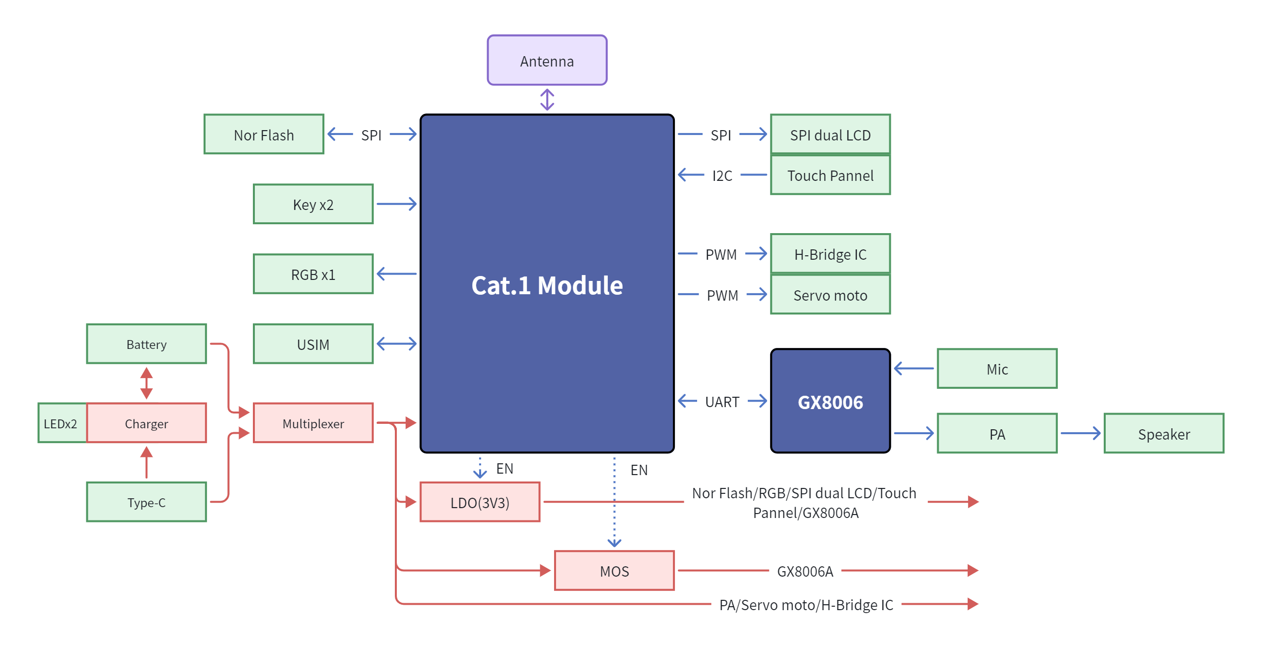
Functional Block Diagram
The Xiaoda functional block diagram is shown below.
Power Supply Methods
The main board is designed with a power switching circuit and can be powered by the following methods:
Powered by Battery The device has an integrated 3.7V lithium battery. Press the power button for 3 seconds to power on.
Powered by Type-C Port Insert the Type-C USB data cable into the USB interface. The system power will automatically switch to Type-C power supply. Press the power button for 3 seconds to power on.
Charging Circuit
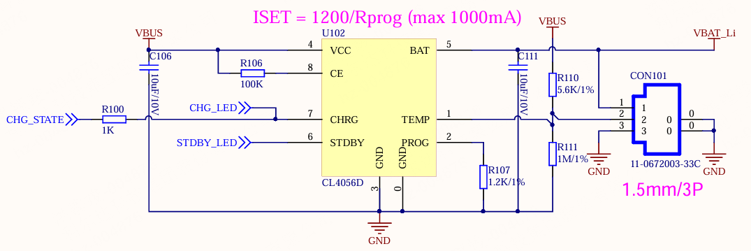 CL4056D maximum charging voltage is 4.2V. NTC recommended to use batteries with R25=100KΩ, with a designable charging range of 0~45℃. When R25=10KΩ, the designable charging range is 0~50℃. As shown in the reference circuit, paired with the 103040A1 battery (R25=10KΩ, B25/50=3435), the designed charging temperature range is 0.46℃~50.22℃. For specific calculation methods, see the table below: NTC Calculation Tool(XLSX)
USB Interface
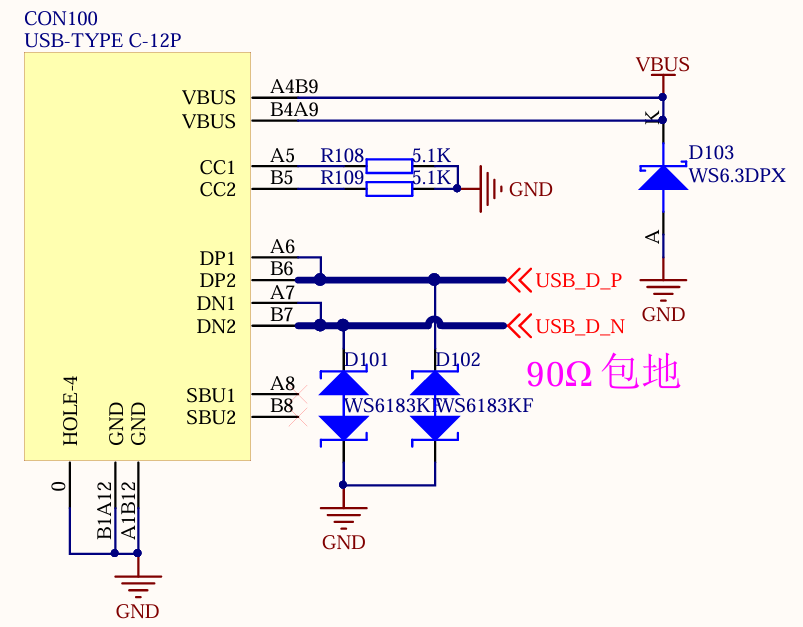 The CC1/CC2 pins of the USB Type-C connector are pulled down to ground through 5.1kΩ resistors by default, configuring the device as a charge-only Sink/Upstream Facing Port (UFP).
SIM Card Interface
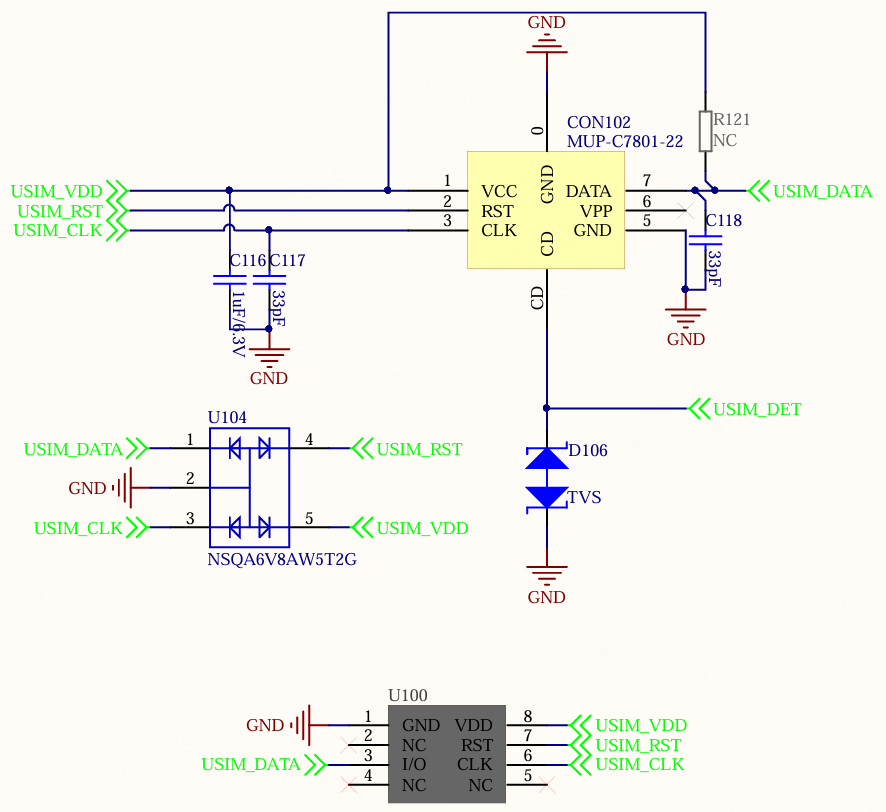 In addition to the SIM card slot, the main board also reserves a chip SIM card footprint. The two overlap in PCB position, and the chip SIM card is used by default.
The chip SIM card provides 500MB of data per month, valid for one year.
In addition to the SIM card slot, the main board also reserves a chip SIM card footprint. The two overlap in PCB position, and the chip SIM card is used by default.
The chip SIM card provides 500MB of data per month, valid for one year.
RF Interface
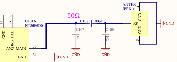 The RF interface reserves an IPEX Gen-1 socket with a reserved π-type matching network. If the antenna needs to be replaced, the matching can be adjusted.
Button Extension Interface
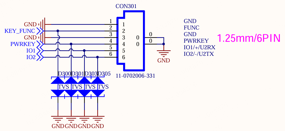 Please note that all button extension IOs have special usage:
The basic function of PWRKEY is as a power on/off button. After powering on, the press duration can be adjusted for use as a function button, e.g., short press for conversation, long press for shutdown
KEY_FUNC is the only button that can be multiplexed as wakeup, with higher interrupt priority. It can also be multiplexed as AGPIO, maintaining state during module sleep
IO1/IO2 are general-purpose IOs with lower interrupt priority, and can be multiplexed as UART for debugging convenience
Motor/Servo Interface
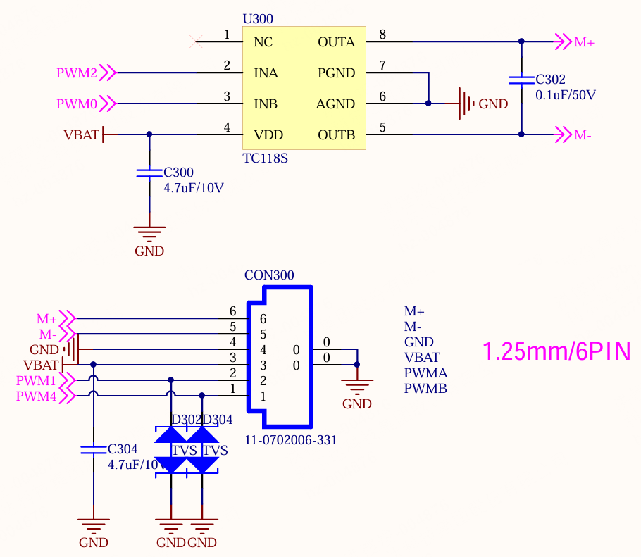 The module provides 4 different PWM channels for motor and servo driving, supporting simultaneous connection of 1 DC motor and 2 servos.
Audio Interface
Offline Voice Chip
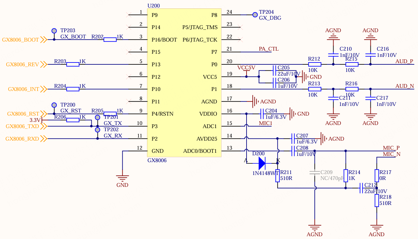 The offline voice chip GX8006A communicates with the module via UART and connects RST/BOOT/INT control pins. Users can perform flashing, playback, recording, and other operations on the GX8006A chip through the NT26F6D0 module.
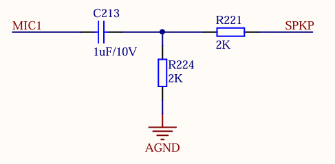 The GX8006A chip supports local AEC. The AEC reference circuit feeds back from the amplifier output through voltage division and DC blocking to GX8006A’s MIC1, performing echo cancellation through AD sampling. If using a Class-D amplifier, the reference path requires multi-stage filtering.
Microphone Interface
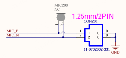 The microphone connector inside Xiaoda already has a microphone inserted. If you need to connect another electret microphone externally, please pay attention to the terminal wire sequence. The microphone cannot be driven if the polarity is reversed.
Speaker Interface
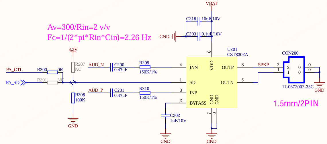 The amplifier gain should match the peak-to-peak value of the preceding audio output and the speaker to avoid volume being too low or clipping distortion. Differential input is recommended for audio input to improve audio anti-interference capability. The amplifier is recommended to operate in Class-AB mode to improve AEC reference performance.
Indicator Light Interface
RGB Indicator Light
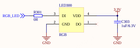 The RGB LED communication interface complies with WS2812 timing.
Charging Indicator Light
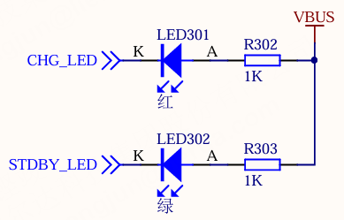 The charging indicator lights up when USB is connected: red light during normal charging, green light when fully charged.
Software Reference
Software Overview
The Xiaoda software is based on the OpenCPU development framework for the L-CT4IT00-YP00W-03A_V04 hardware, adopting an event-driven Job scheduling architecture to implement voice wake-up, AI conversational interaction, network management, power management, and other functions.
Software Version: V02.00.01
AI Platform: Coze Real-time Voice Conversation
Audio Codec: Opus, 16KHz sampling rate
Communication Protocol: WebSocket (wss)
Software Architecture
┌───────────────────────────────────────────────────┐
│                    user_main.c                    │
├───────────────────────────────────────────────────┤
│                  app_framework                    │
│  ┌──────────┬──────────┬──────────┬────────────┐  │
│  │ talk_job │ powerkey │ network  │ led_sidejob│  │
│  └──────────┴──────────┴──────────┴────────────┘  │
│                   global_policy                   │
├───────────────────────────────────────────────────┤
│                     peripheral                    │
│  ┌─────────┬────────┬────────┬──────┬──────────┐  │
│  │ai_connect│ audio │battery │ led  │ ldoPower │  │
│  ├─────────┼────────┼────────┼──────┼──────────┤  │
│  │ network │powerkey│location│      │          │  │
│  └─────────┴────────┴────────┴──────┴──────────┘  │
├───────────────────────────────────────────────────┤
│                  LIOT SDK / RTOS                  │
└───────────────────────────────────────────────────┘
Directory Structure
examples/CT4IT00YP00W_03/
├── src/
│   ├── user_main.c              # Application entry
│   └── app_nv.c                 # NV parameter storage management
├── inc/
│   ├── app_nv.h                 # NV data structure definition/pin definition/default config
│   └── user_main.h              # Entry header file
└── framework/
    ├── common/
    │   ├── inc/app_framework.h  # Framework interface
    │   └── src/
    │       ├── app_framework.c  # Framework initialization and Job registration
    │       ├── talk_job.c       # AI conversation Job
    │       ├── powerkey_job.c   # Power button Job
    │       ├── network_job.c    # Network management Job
    │       ├── led_sidejob.c    # LED indicator SideJob
    │       └── global_policy.c  # Global event dispatch policy
    ├── peripheral/
    │   ├── ai_connect/          # AI cloud connection (Coze WebSocket)
    │   ├── audio/               # Audio module (GX8006A control)
    │   ├── battery/             # Battery management (ADC sampling/charge detection)
    │   ├── led/                 # WS2812B RGB LED driver
    │   ├── ldoPower/            # LDO power control
    │   ├── network/             # Network registration and status management
    │   ├── powerkey/            # Power button detection
    │   └── location/            # Base station positioning
    └── resource/
        ├── audio_prompts.c      # Prompt tone Opus data
        └── audio_prompts.h      # Prompt tone enum definition
Core Framework Mechanisms
Event-Driven Model
The system adopts an event-driven architecture where all modules communicate through an event bus:
Event |
Description |
Source |
|---|---|---|
EVT_KEY_POWER_ON |
Power on event |
powerkey module |
EVT_KEY_POWER_OFF |
Power off event |
powerkey module |
EVT_KEY_WAKEUP |
Button wake-up |
powerkey module |
EVT_AUDIO_WAKEUP |
Voice wake-up |
GX8006A offline voice chip |
EVT_AUDIO_RECORD_DONE |
Recording complete (VAD silence detection) |
audio module |
EVT_AUDIO_PLAY_START |
Start playing AI response |
audio module |
EVT_AUDIO_PLAY_DONE |
AI response playback complete |
audio module |
EVT_AI_CONNECT_REQ |
Request AI cloud connection |
network_job |
EVT_AI_CONNECTED |
AI cloud connection successful |
ai_connect module |
EVT_AI_CONNECT_FAIL |
AI cloud connection failed |
ai_connect module |
EVT_AI_DISCONNECTED |
AI cloud disconnected |
ai_connect module |
EVT_AI_RESPONSE_DONE |
AI response ended |
ai_connect module |
EVT_NETWORK_READY |
Network registration successful |
network module |
EVT_NETWORK_FAIL |
Network registration failed |
network module |
EVT_SIM_ERROR |
SIM card error |
network module |
EVT_LOW_POWER |
Low battery |
battery module |
EVT_SYSTEM_SLEEP |
System sleep |
idle timeout |
EVT_TIMER_EXPIRED |
Timer expired |
framework timer |
Job Scheduling
The framework supports two types of Jobs:
Main Job: Only one main Job is active at any time; multiple main Jobs are mutually exclusive
SideJob: Runs persistently in the background, receives all events, does not participate in main Job mutual exclusion scheduling
Currently registered Jobs:
Job |
Type |
Function |
|---|---|---|
talk_job |
Main Job |
Full AI conversation flow: initialize audio → connect AI → record → send → receive → play |
powerkey_job |
Main Job |
Handles power on/off, low battery shutdown, sleep |
network_job |
Main Job |
Handles network status changes, triggers AI connection when network is ready |
led_sidejob |
SideJob |
Controls RGB LED effects based on system status, manages idle timeout |
Global Policy
The global policy determines how events are dispatched to Jobs:
Voice wake-up/AI connection request → Interrupt current Job, start talk_job
Power button/Low battery/Sleep → Interrupt current Job, start powerkey_job
Network status change → If current Job is not network/talk Job, start network_job
Audio events/AI events/Timer → Deliver to the currently active Job for handling
Core Module Description
AI Connection Module (ai_connect)
Connects to the Coze real-time voice conversation platform based on WebSocket protocol:
Uses libwebsockets library to establish wss connection
Audio uplink: PCM → Opus encoding → Base64 → JSON encapsulation and send
Audio downlink: JSON parsing → Base64 decoding → Opus frames → audio module playback
Supports chat.update to configure audio parameters and subscribe to events
Supports conversation.chat.requires_action to handle AI tool calls
Audio Module (audio)
Controls the GX8006A offline voice chip via UART (1Mbps):
Voice wake-up: GX8006A notifies the module via INT pin after local wake-up
Recording: GX8006A transmits PCM data via UART after AEC echo cancellation
Playback: Module sends Opus frames to GX8006A via UART for decoding and playback
Local prompt tones: power on/off, connection success/failure, wake-up, etc.
Power Management Module (ldoPower)
Controls the power supply sequence of peripheral devices:
Enable AON power domain
Set all power domain voltages to 3.3V
Pull LDO33_EN (GPIO25) high to enable external LDO
Control GX8006A power pin (GPIO26) to power up
Battery Module (battery)
[!NOTE] Note Due to missing hardware components, this feature is currently unavailable.
ADC sampling of battery voltage (channel 1)
USB insertion detection (GPIO14)
Low battery warning and automatic shutdown
LED Module (led)
Drives WS2812B RGB LED via SPI, supporting the following light effect modes:
Mode |
Effect |
Corresponding Status |
|---|---|---|
LED_PATTERN_STANDBY |
Solid green |
Standby/Idle |
LED_PATTERN_LISTENING |
Flashing blue |
Recording |
LED_PATTERN_THINKING |
Breathing blue |
AI processing |
LED_PATTERN_SPEAKING |
Flashing blue |
AI response playing |
LED_PATTERN_ERROR |
Solid red |
Network/Connection error |
LED_PATTERN_POWEROFF |
Green flash 3 times |
About to shut down |
NV Parameter Configuration
System parameters are defined in app_nv.h:
Coze parameter configuration requires creating your own agent first. See https://www.coze.cn For the location token, please contact frontline colleagues.
Parameter |
Default Value |
Description |
|---|---|---|
coze_token |
(built-in) |
Coze Platform API Token |
coze_botid |
(built-in) |
Coze Bot ID |
coze_voiceid |
(built-in) |
Coze Voice Character ID |
chat_mode |
0 |
Conversation mode |
audio_volume |
80 |
Volume (0~100) |
sleep_wait_time_ms |
60000 |
Idle prompt wait time |
sleep_time_ms |
60000 |
Auto shutdown time after idle |
Main Flow
Power On (Long press PWRKEY)
        │
        ▼
Power Initialization (LDO/GX8006A power up)
        │
        ▼
Framework Init → Register Job/SideJob/Policy
        │
        ▼
Play power-on prompt tone
        │
        ▼
Network Registration ────────── Fail → Play connection failed prompt/LED red
        │ Success
        ▼
Play network connection success prompt
        │
        ▼
WebSocket Connect Coze ──────── Fail → Play connection failed prompt/LED red
        │ Success
        ▼
Play AI connection success prompt / Start recording
        │
        ▼
┌─── Wait for "Hello Xiaoda" voice wake-up (GX8006A local) ◀──────┐
│       │                                                          │
│       ▼                                                          │
│   Play wake-up response prompt (ding-dong)
│       │                                                          │
│       ▼                                                          │
│   Recording (GX8006A AEC + VAD)
│       │                                                          │
│       ▼                                                          │
│   VAD silence detected → Audio upload complete
│       │                                                          │
│       ▼                                                          │
│   Wait for AI response (LED thinking state)
│       │                                                          │
│       ▼                                                          │
│   Receive audio stream → Playback (LED speaking state)
│       │                                                          │
│       ▼                                                          │
│   Playback complete → Return to standby (LED green) ─────────────┘
│
├── Idle timeout → Play "Need more help?" → No response wait 10s → Play shutdown prompt → Shutdown
│
└── Long press PWRKEY → Play shutdown prompt → Shutdown
Build and Flash
Build
Execute in the SDK root directory:
#Windows build
build.bat PROJECT=CT4IT00YP00W_03 MODEM=NT26F6D0 all
#Linux build
make PROJECT=CT4IT00YP00W_03 MODEM=NT26F6D0 all
Build output: gccout/CT4IT00YP00W_03/CT4IT00YP00W_03_NT26F6D0.binpkg
Flash
Connect PC and Xiaoda using a USB data cable
Long press the power button to power on
Use the Lierda download tool to select the
CT4IT00YP00W_03_NT26F6D0.binpkgfile for flashingAfter flashing is complete, press the Reset button or power on again